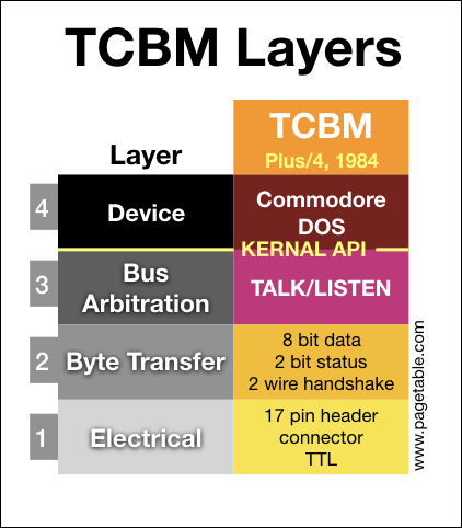
In the series about the variants of the Commodore Peripheral Bus family, this article covers the lowest two layers (electrical and byte transfer) of the “TCBM” bus as found on the TED series computers: the C16, C116 and the Plus/4.
NOTE: I am releasing one part every week, at which time links will be added to the bullet points below. The articles will also be announced on my Twitter account @pagetable and my Mastodon account @pagetable@mastodon.social.
- Part 0: Overview and Introduction
- Part 1: IEEE-488 [PET/CBM Series; 1977]
- Part 2: The TALK/LISTEN Layer
- Part 3: The Commodore DOS Layer
- Part 4: Standard Serial (IEC) [VIC-20, C64; 1981]
- Part 5: TCBM [C16, C116, Plus/4; 1984] ← this article
- Part 6: JiffyDOS [1985] (coming soon)
- Part 7: Fast Serial [C128; 1986] (coming soon)
- Part 8: CBDOS [C65; 1991] (coming soon)
Naming
The only computers with a TCBM bus are the Commodore C16, C116 and Plus/4. Internally, Commodore called these the TED series, named after the core IC of the system1. This name can be seen in multiple places in the TED KERNAL and BASIC sources as well as internal documentation. Even though Commodore never marketed these computers under the name TED, many products around them, like software cartridges, had product codes prefixed with “T”2.
The naming for the new peripheral bus of the TED is not completely consistent:
- Comments in the KERNAL driver code call it the Kennedy or KDY interface – a reference to the politician. Some places call it TEDISK.
- The 1551 power-on message is “CBM DOS 2.6 TDISK”, which seems a variant of “TEDISK”.
- The users manual and the schematics of the 1551 disk drive call it TCBM. “CBM” is the common abbreviation of “Commodore Business Machines”, and the “T”, as always, stands for “TED”.
History and Development
The Commodore PET (1977) was using the industry-standard 8-bit parallel IEEE-488 bus for disk drives and printers. For the VIC-20 (1981), Commodore changed layers 1 and 2 of the protocol stack (electrical and byte transfer) into a cheaper serial bus, which turned out to have severe speed problems3.
For the TED series (1984), Commodore decided to create another variant of the protocol stack, replacing layers 1 and 2 again. The new bus was supposed to combine the speed of the IEEE-488 bus with the low cost of the serial bus.
While the switch from parallel IEEE-488 to serial allowed the protocol stack to retain all key properties of the original design, TCBM drops some of these features:
| Feature | IEEE-488 | Serial | TCBM |
|---|---|---|---|
| All participants are daisy-chained. | Yes | Yes | No |
| One dedicated controller (the computer) does bus arbitration of up to 31 devices. | Yes | Yes | No |
| One-to-many: Any participant can send data to any set of participants. | Yes | Yes | No |
| A device has multiple channels for different functions. | Yes | Yes | Yes |
| Data transmission is byte stream based. | Yes | Yes | Yes |
A device still has multiple channels, and all data transmission is still byte stream based, because these are properties of the layers 3 and 4, which are retained in TCBM.
The key difference is that the TCBM bus is point-to-point: The bus is between one controller (the computer) and one device. For connecting multiple devices to one computer, the computer needs one dedicated bus per device.
With the introduction of Fast Serial with the C128, Commodore gave up the TCBM bus, which had only shipped with the TED series.
Layer 1: Electrical
Connectors and Pinout
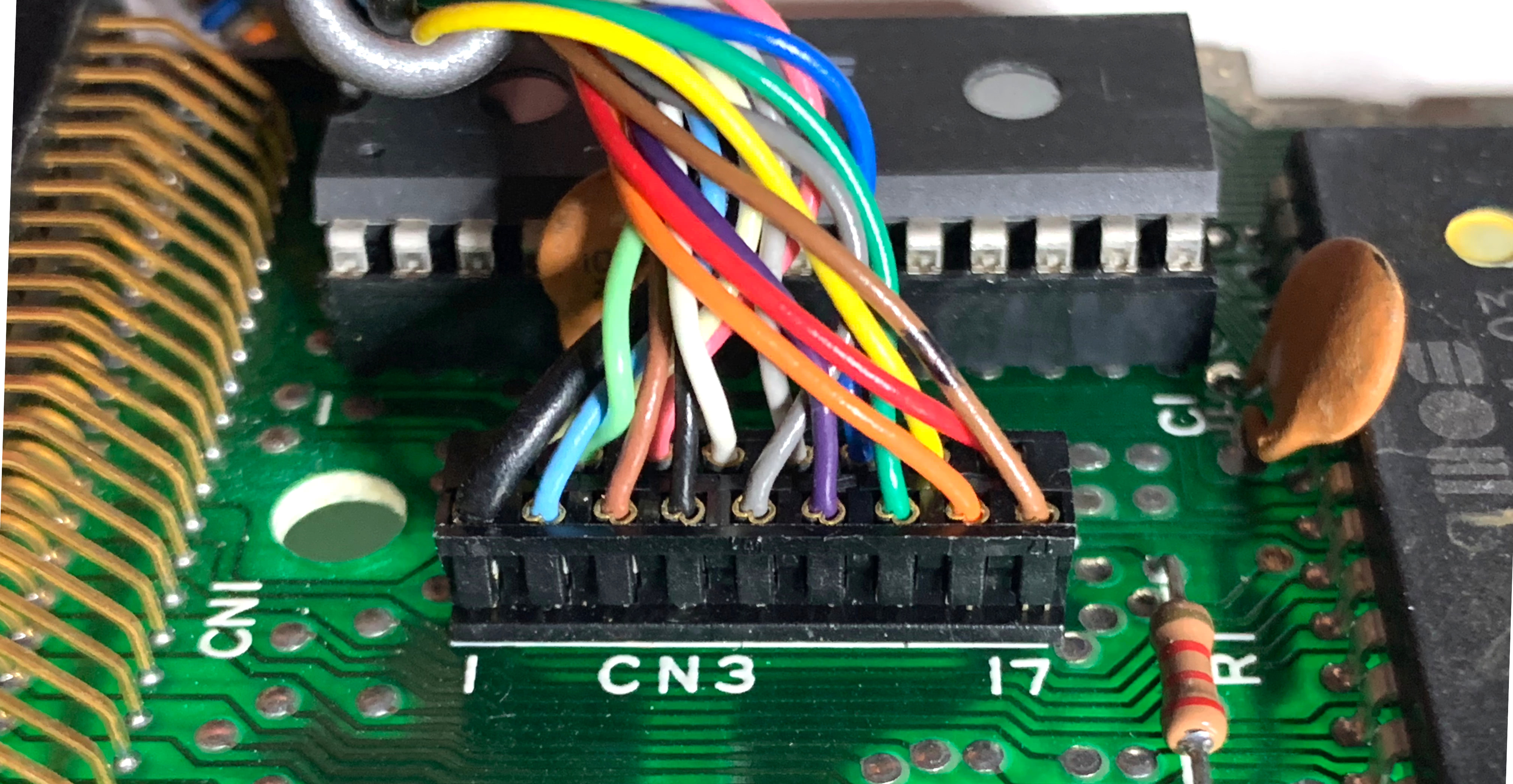
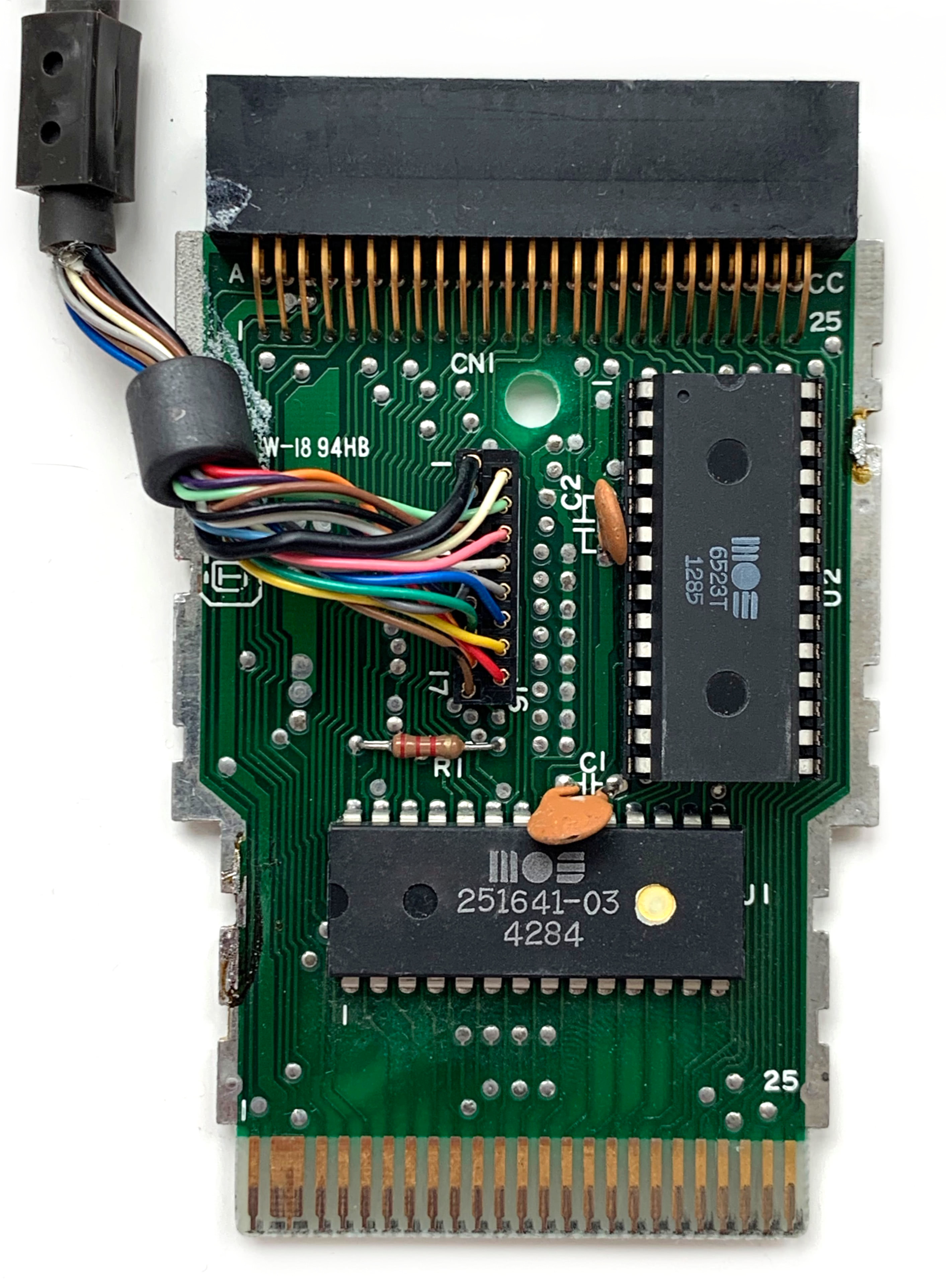
There are no standardized connectors. Both on the computer and the device side, the 17 wires are connected directly to the board through pin headers. This is the computer side:
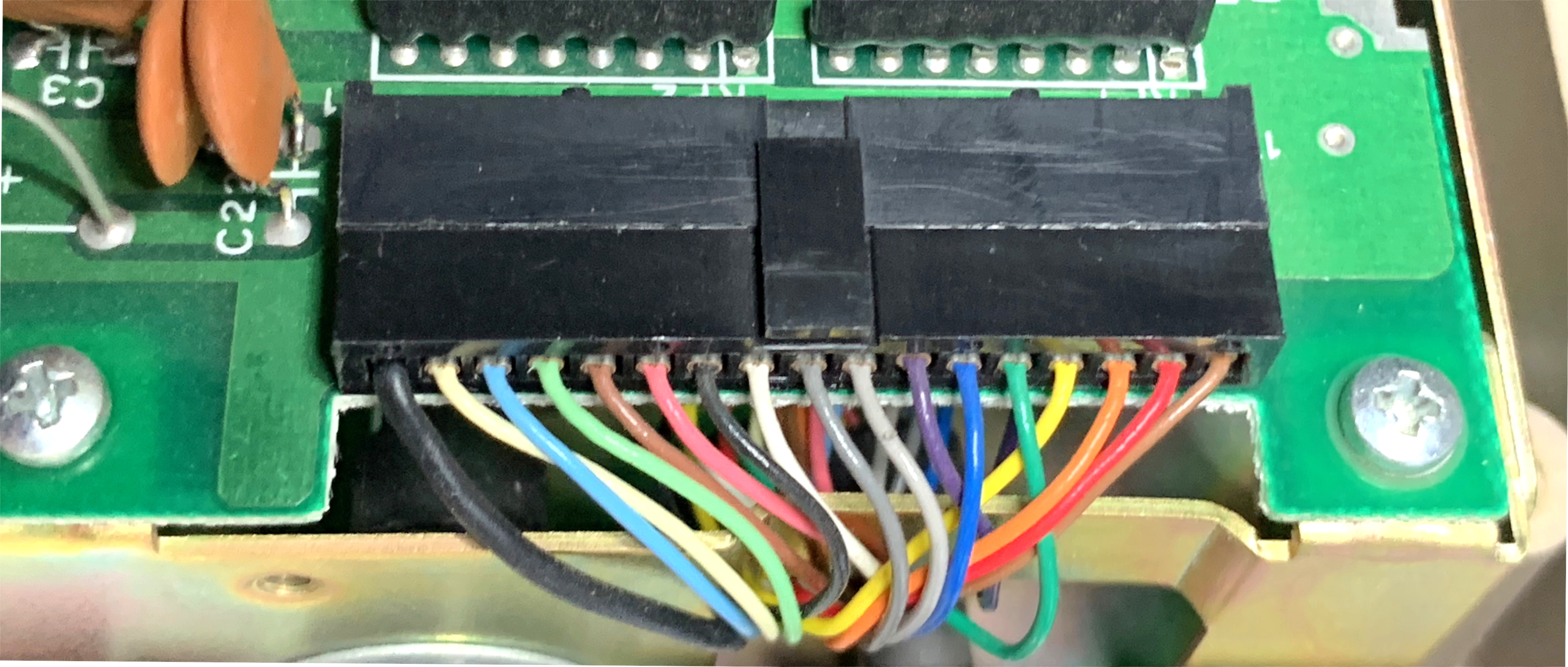
And the device side:
This is the pinout:
| Pin | Signal | Description |
|---|---|---|
| 1 | GND | Ground |
| 2 | DEV | Device 0/1 |
| 3 | DIO1 | Data I/O |
| 4 | DIO2 | Data I/O |
| 5 | DIO3 | Data I/O |
| 6 | DIO4 | Data I/O |
| 7 | DIO5 | Data I/O |
| 8 | DIO6 | Data I/O |
| 9 | DIO7 | Data I/O |
| 10 | DIO8 | Data I/O |
| 11 | DAV | Data Valid |
| 12 | STATUS0 | Status 0 |
| 13 | ACK | Acknowledge |
| 14 | STATUS1 | Status 1 |
| 15 | RESET | Reset |
| 16 | GND | Ground |
| 17 | GND | Ground |
- There are 8 data lines, DIO1-84.
- The two STATUS lines are used by the device to signal errors.
- The DAV and ACK lines are used for handshaking.
- The RESET line resets the device.
- The DEV line tells the paddle whether to create bus #0 or #1 (see below).
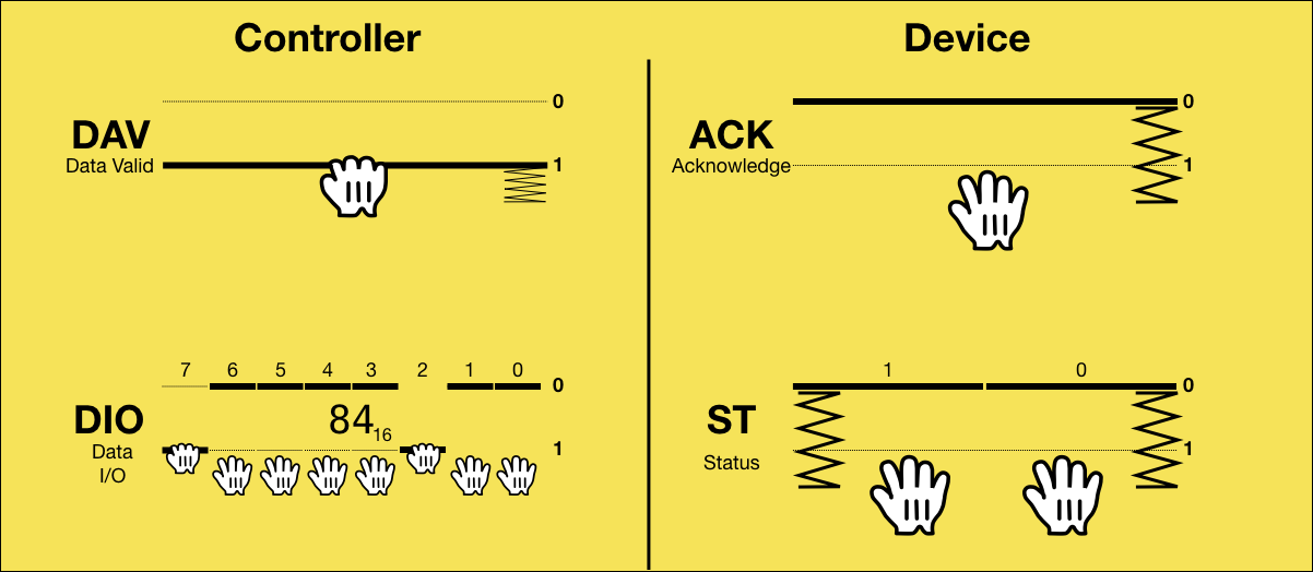
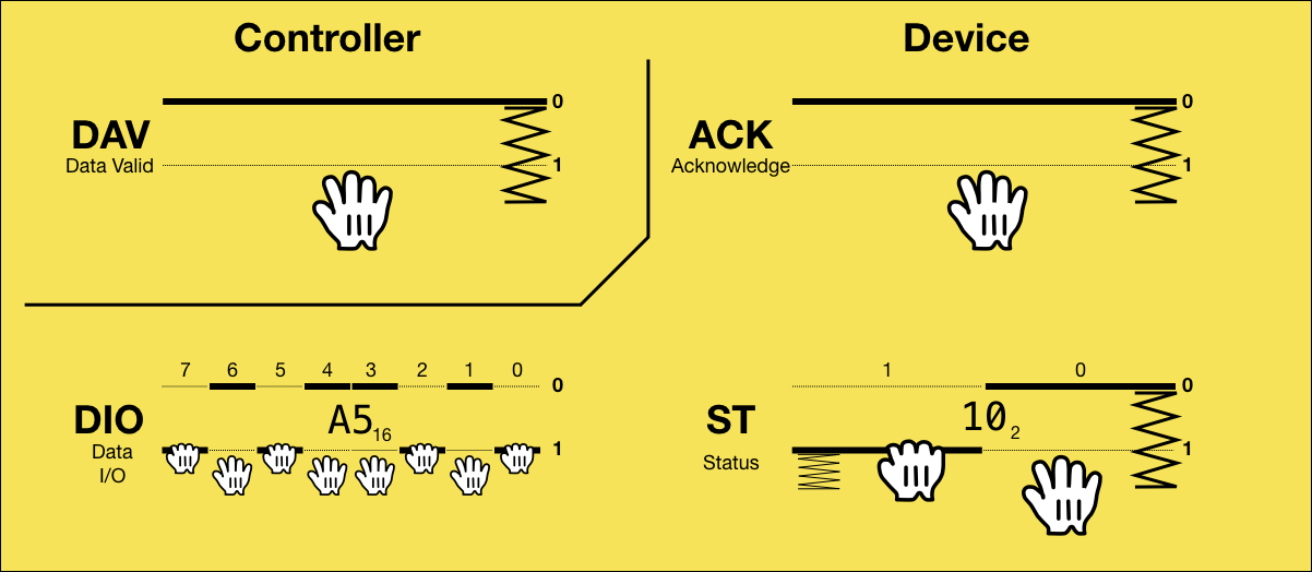
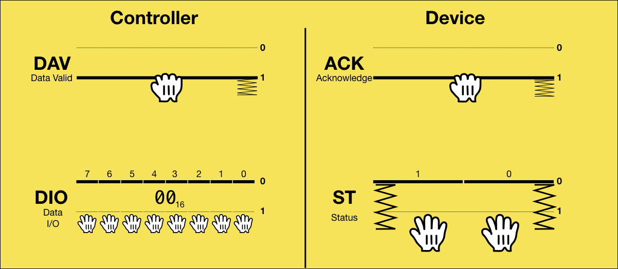
Open Collector Logic
The DIO lines are TTL open collector, which means:
- Both participants of the bus can not only read, but also write to the line.
- When both participants write 0, the line will read back 0, but if either device writes 1, the bus will read back as 1.
- The logic is inverted: 5V is 0 (false), and 0V is 1 (true).
In other words: If the line is released by both bus participants, it will be 5V (logically 0), and either participant can pull it to 0V (logically 1).
This can be visualized with two hands that can pull the line to 1, and a spring that pushes it to 0:
So when a line reads as 0, it is known that it is currently released by all participants, and if a line reads as 1, one or more participants are pulling it, but it is impossible to know who or even how many.
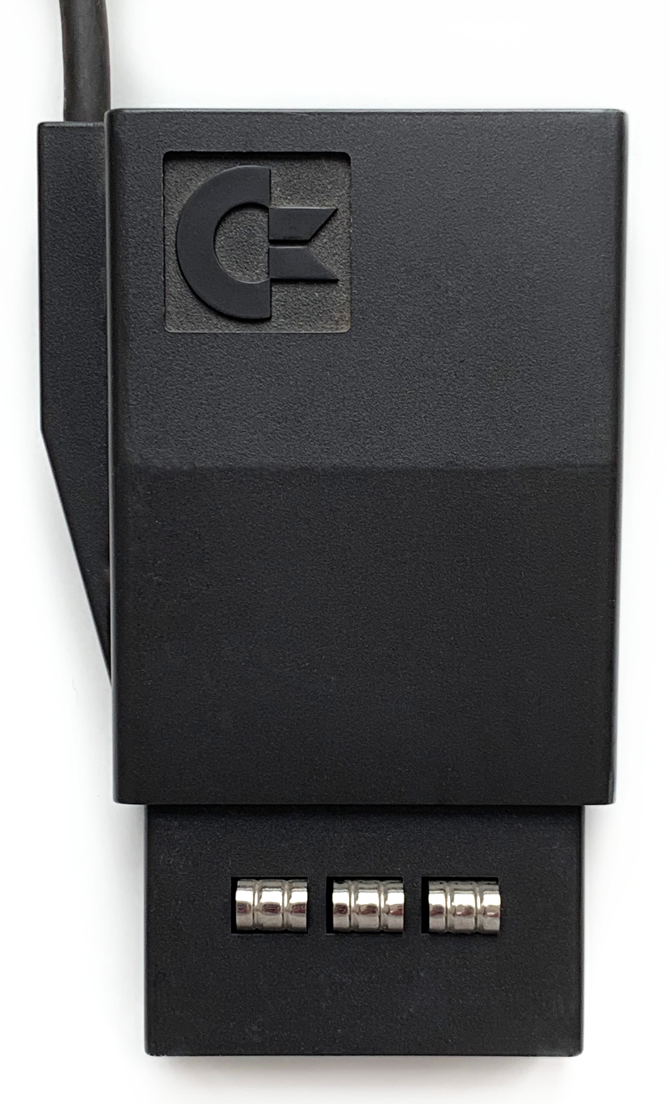
Paddle
The TED series spans from the super-low-cost5 C116 (rubber keyboard, 16 KB) to the high-end Plus/4 (pro keyboard, 64 KB, RS232, built-in productivity software). The Standard Serial port only requires 3 GPIO lines and was natively supported by all TED machines. A parallel bus would have required adding an additional I/O controller.
To save on costs, the I/O controller did not come with the computer. Instead, it shipped with the disk drive, where the costs of the chip were eclipsed by the total cost of the drive (USD 269).
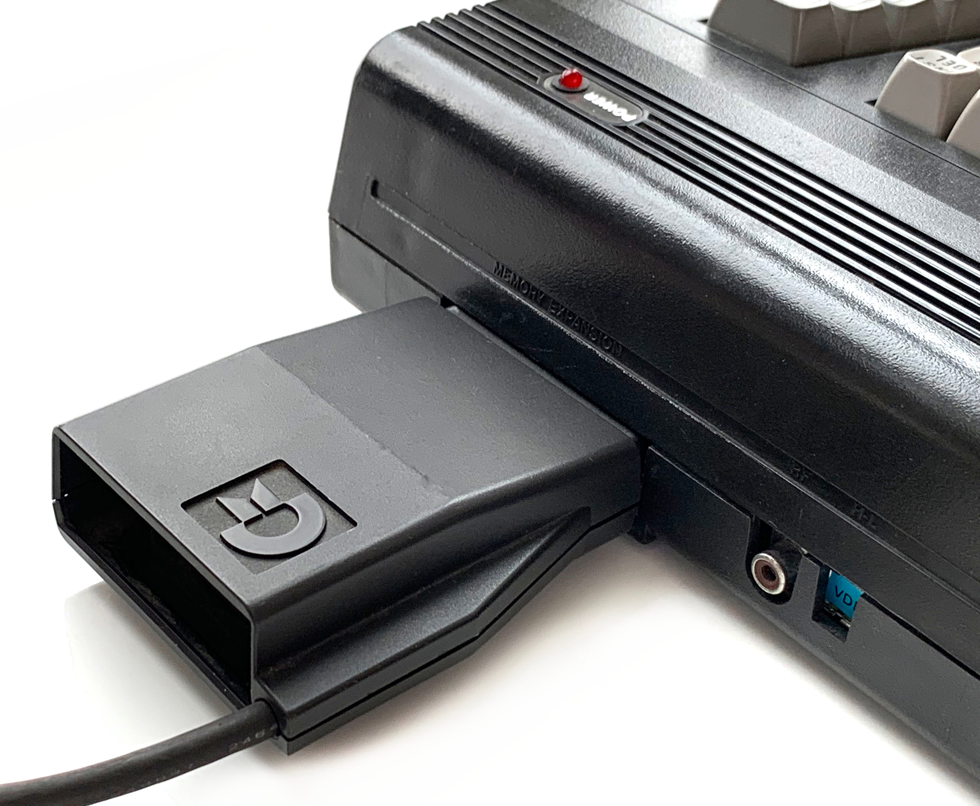
The 1551 disk drive, the only TCBM device made, came with a fixed cable that ended in the so-called “Paddle”, a cartridge for the TED expansion port. The expansion port on Commodore computers exposes the complete internal bus, allowing the I/O controller in the paddle to map itself into the computer’s address space.
Each paddle has a pass-through connector to allow using any other cartridge at the same time – or to connect a another paddle.
A second 1551 required its own paddle on top of the first one. In this setup, there is one I/O controller in each paddle, which is mapped to one of two locations in the computer’s address space. A switch in the disk drive tells the paddle through the DEV line which location and thus which device number the drive should have6.
Multiple Busses
The TED computers support the Standard Serial bus and send all traffic to devices 4-30 to this bus. If a paddle with DEV = 0 is detected, it will direct traffic to drive 8 to this TCBM bus. And if there is a paddle with DEV = 1, all traffic to drive 9 will go to that TCBM bus. This allows a TED to have up to three separate Commodore Peripheral busses. All participants of the Standard Serial bus can talk to each other, but the TCBM busses are point-to-point7.
The presence of a TCBM device is detected8 whenever a communication channel is initiated (layer 3 TALK or LISTEN) for devices 8 or 9.
Layer 2: Byte Transfer
The byte transfer layer of TCBM defines the roles of the controller (which is the computer) and the device.
The controller and the device each own one handshaking line: DAV and ACK, respectively. The names stand for “Data Valid” and “Acklowledge”, but in practice, they are just general handshaking lines with different meanings across the protocol.
The device also owns the two STATUS lines to communicacte error codes to the controller. The eight DIO lines are shared and used to send data in either direction. The protocol defines at what point which participant owns it.
All communication is initiated by the controller by telling the device whether data is sent to it or received from it, or whether a layer 3 command is sent to the device.
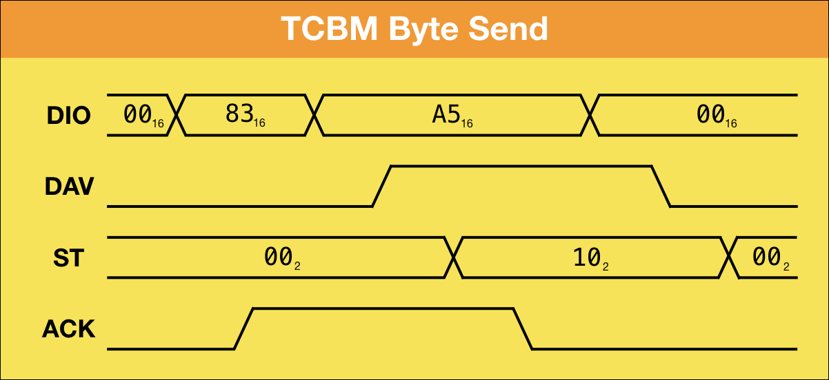
Sending Bytes
When the controller sends data to the device, it owns the eight DIO lines during the whole process. The basic idea is that the controller sends a TCBM code of 0x83 to indicate a byte send, then sends the byte, and the device returns a two-bit status code.
Let’s go through it step by step:
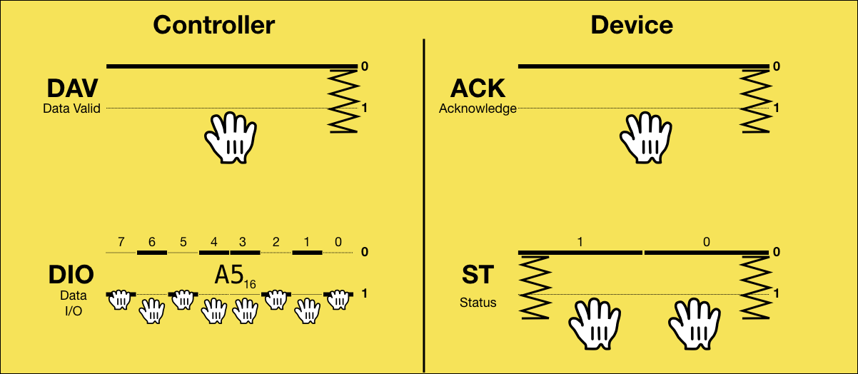
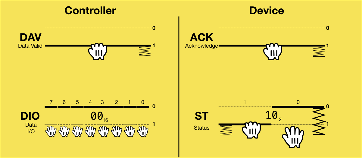
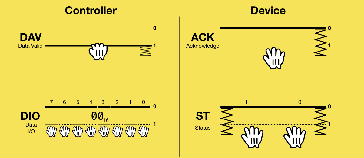
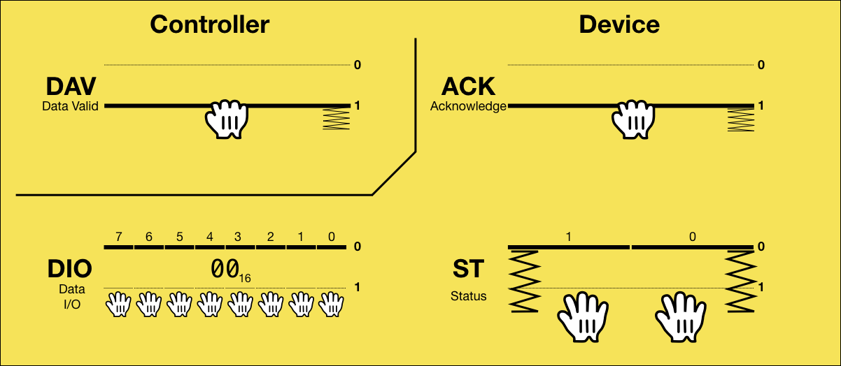
0: Initial State

In the initial state, the controller is holding the DAV line to indicate that it it is not ready for the next transmission. The device is holding the ACK line, meaning it is not ready either. The DIO and ST lines are all released.
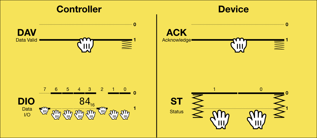
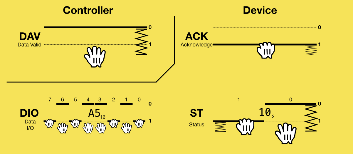
1: Controller puts code 0x83 on the bus
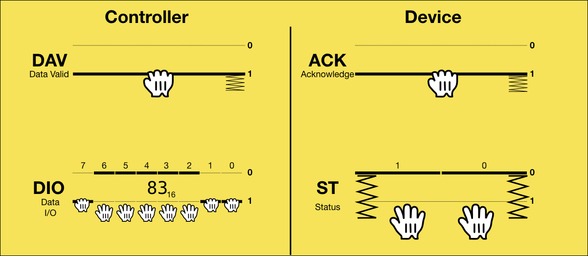
All communication is initiated by the controller by putting a TCBM code byte onto DIO. 0x83 means that the controller intends to send a byte to the device.
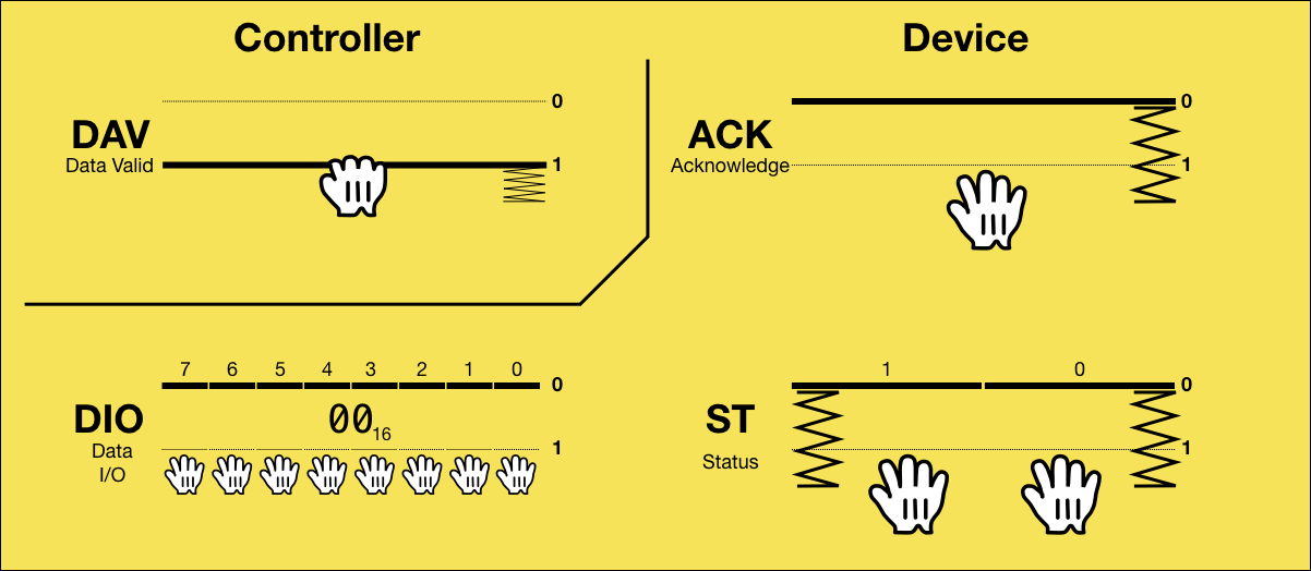
2: Device has accepted the code
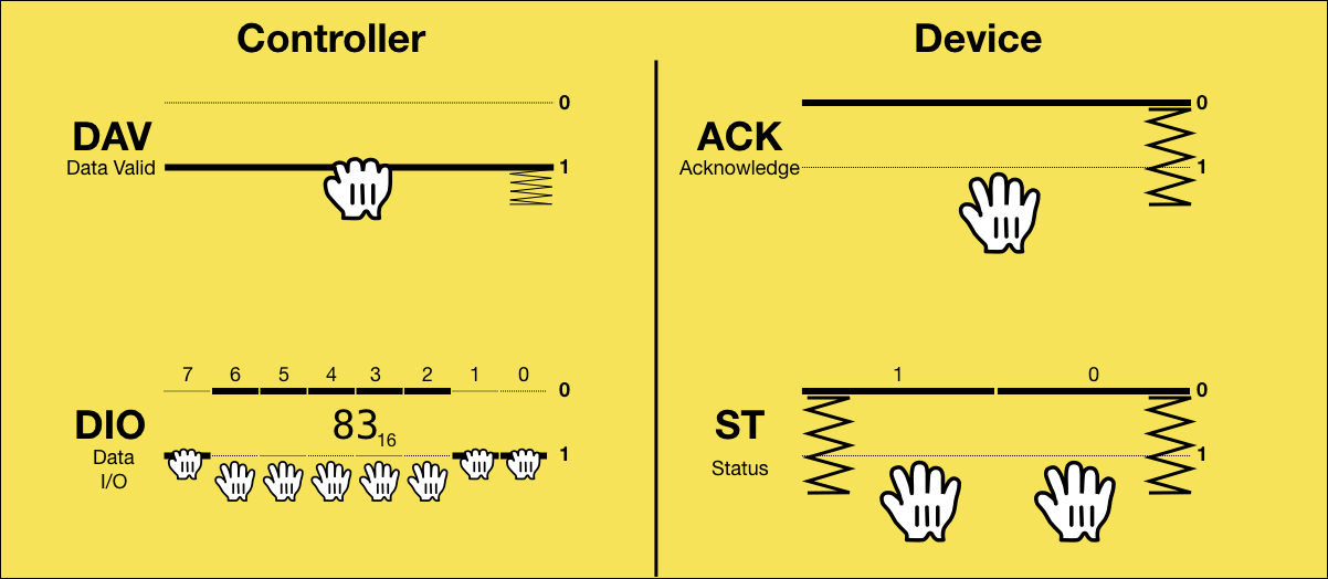
At some point the device is done handling the previous byte it may have received, so it detects that the most significant bit of DIO is set, reads the TCBM code, and signals that it has received the code by releasing ACK.
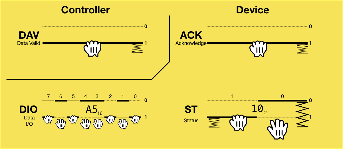
3: Controller puts data on the bus
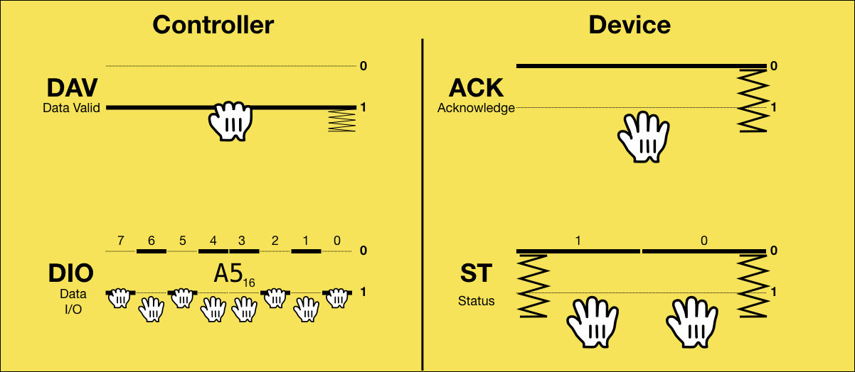
Triggered by ACK being 0, the controller now puts the byte value onto DIO.
4: Data on bus is now valid
After that, the controller releases DAV, signaling that the data in DIO is valid.
5: Device puts status on the bus
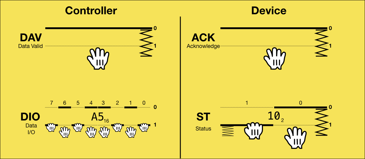
Triggered by DAV being 0, the device reads the data from DIO and puts the two status bits onto ST.
6: Device has accepted the data, status is valid
It then pulls ACK, signaling that it has accepted the data and that the status is valid.
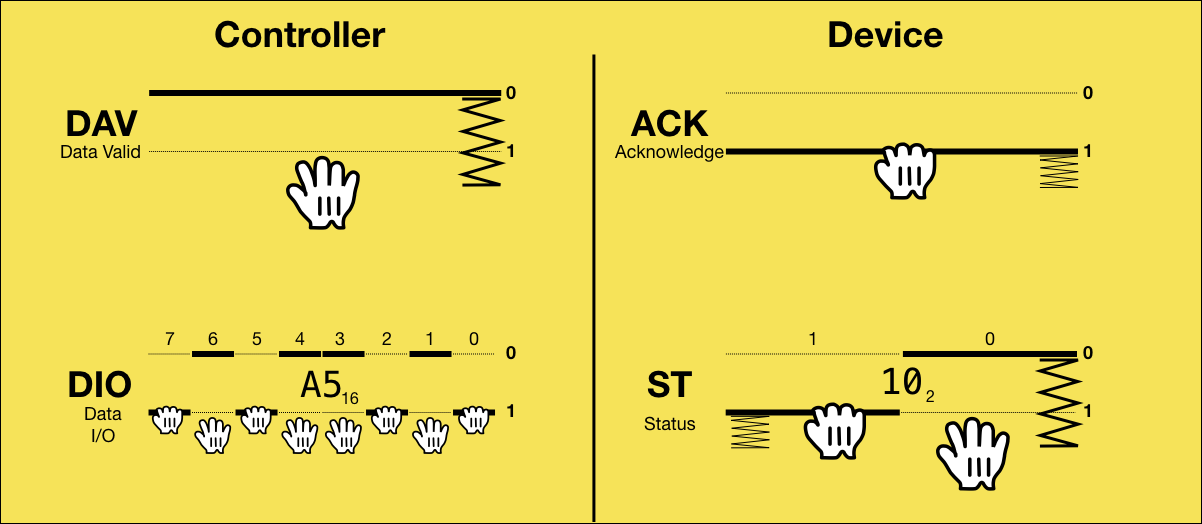
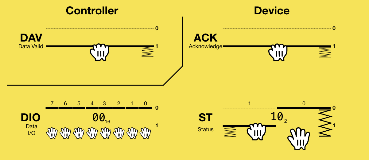
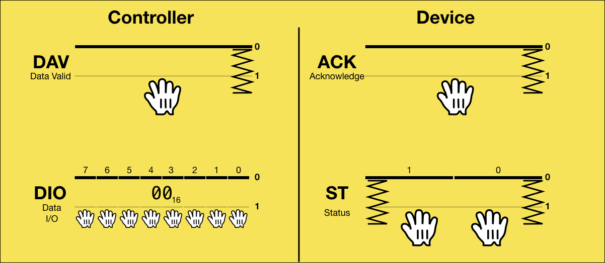
7: Controller clears data on the bus
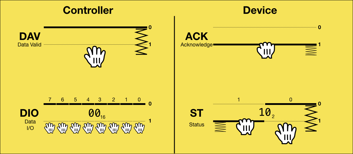
Triggered by ACK being 1, the controller reads the status, and sets the DIO lines back to 0, so they can’t be interpreted as a TCBM code in the next cycle.
8: Controller resets data valid
In order to return to the initial state, the sender then pulls DAV.
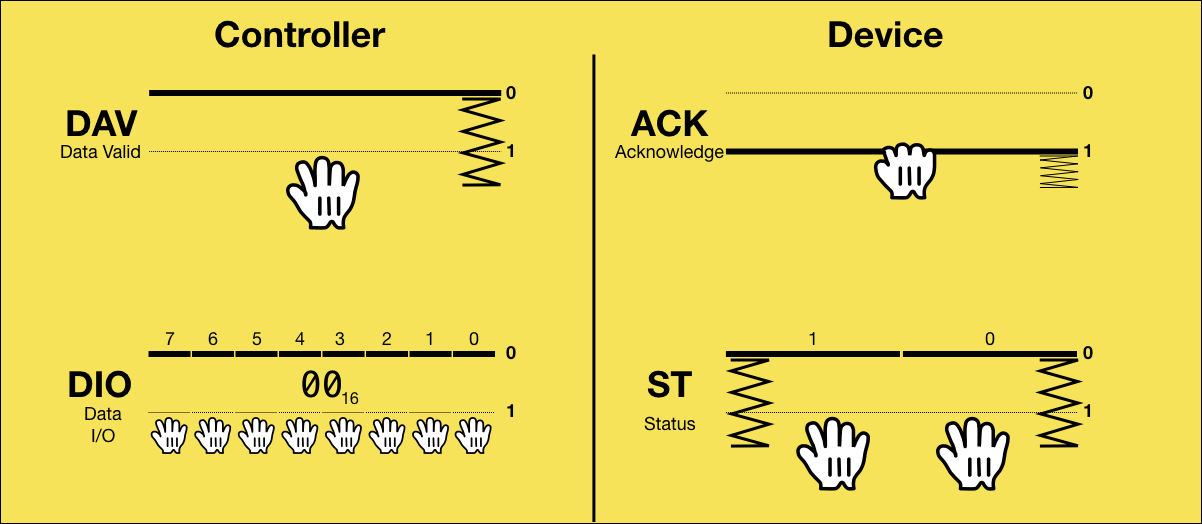
9: Device resets status

Triggered by DAV being 1 (the controller has read the status), the device clears the status. All wires are now in the initial state again. All steps are repeated as long as there is more data to be sent.
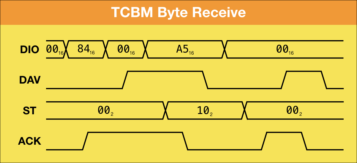
Receiving Bytes
When the controller wants to receive data from the device, ownership of the eight DIO lines is passed to the device and back. The basic idea is that the controller sends a TCBM code of 0x84 to indicate a byte receive, passes DIO to the device, the device returns the byte and a two-bit status code, and DIO is passed back to the controller.
Here it is step by step:
0: Initial State

The initial state between bytes when receiving is the same as when sending: The controller is holding the DAV line to indicate that it it is not ready for the next transmission and the device is holding the ACK line, meaning it is not ready either. The DIO and ST lines are all released.
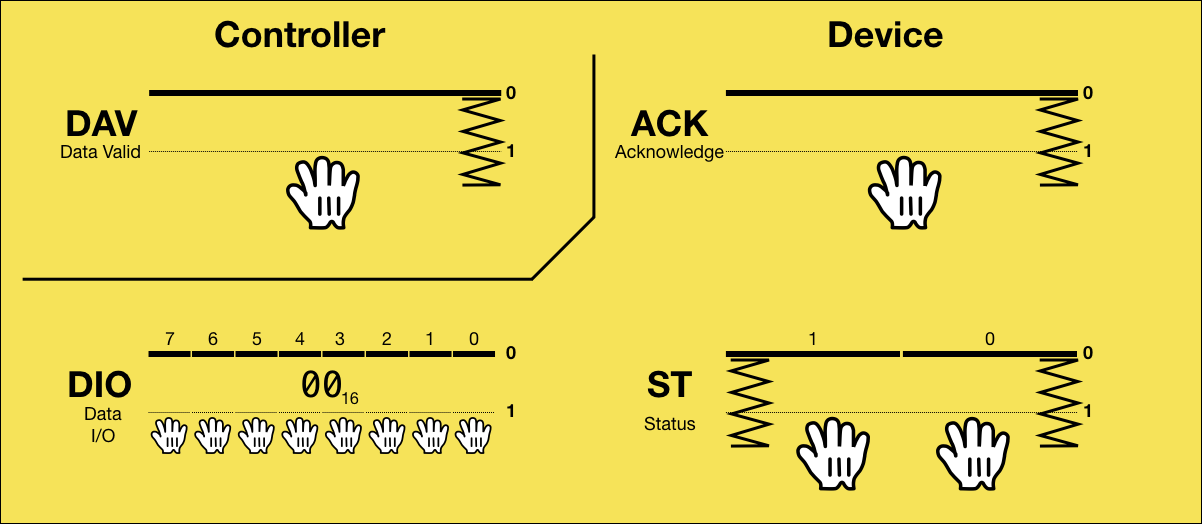
1: Controller puts code 0x84 on the bus
For receiving, the controller puts the TCBM code of 0x84 into DIO, indicating that it is now ready to receive a byte.
2: Device has accepted the code
As soon as the device is done handling the last transmission, it detects that the most significant bit of DIO is set, reads the TCBM code, and signals that it has received the code by releasing ACK.
3: Controller clears data on the bus
For the transmission of the data, the DIO lines will be operated by the device, so triggered by ACK being 0 (the device has received the code), the controller releases all DIO lines.
4: Controller signals DIO belongs to device
To signal that the DIO lines now belong to the device, the controller then releases DAV.
5: Device puts data on the bus
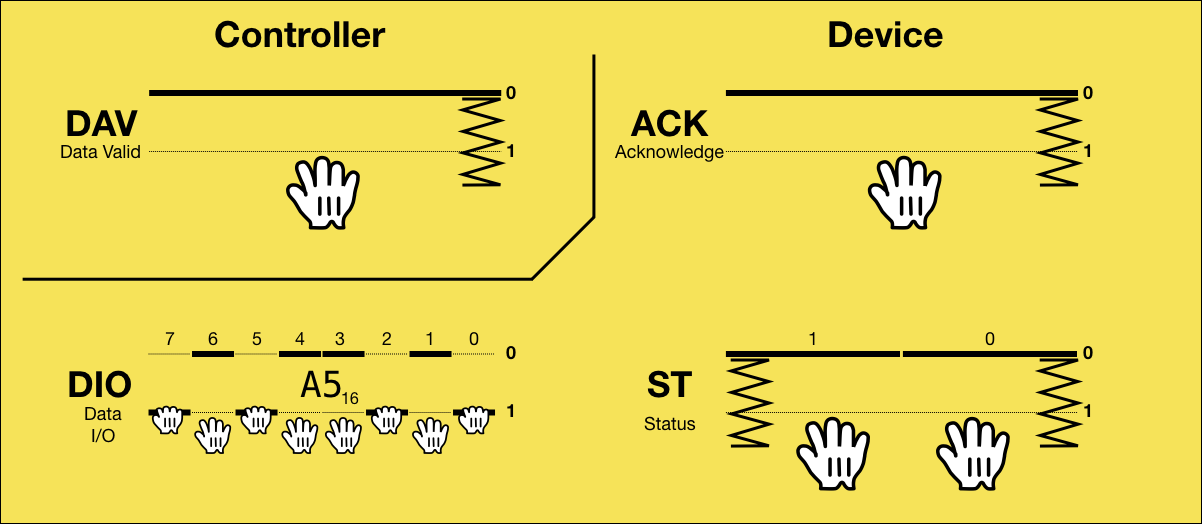
Triggered by DAV being 0, the device puts the data onto DIO.
6: Device puts status on the bus
It also puts the status bits onto ST.
7: Data on bus is now valid
After that, the device pulls ACK, signaling that the data in DIO is valid.
8: Controller has accepted the data
Triggered by ACK being 1, the controller reads the data and the status from DIO and pulls DAV, indicating that it has accepted the data.
9: Device clears data on the bus
Triggered by DAV being 1, the device clears the data from DIO, in order to return ownership of these lines to the controller.
10: Device clears status
It then resets the status lines, so they are in the initial state again.
11: Device signals it is done with DIO
Finally, it releases ACK to indicate that it is no longer using DIO.
12: Controller signals it owns DIO
Triggered by ACK being 0, the controller releases DAV, meaning it now owns the DIO lines again.
13: Device returns to initial state
Triggered by DAV being 0, the device pulls ACK, which is the initial state.
14: Controller returns to initial state
Triggered by ACK being 1, the controller pulls DAV. All wires are now in the initial state again. All steps are repeated as long as there is more data to be received.
Note that the protocol only specifies the triggers: For example, the controller is to read the data from DIO once ACK = 1, so it would be just as legal for the the device to put the status on the bus before the data, or put both the status and the data on the bus and pull ACK at the same time.
Sending Commands
Layer 3 of the protocol stack requires the controller to send commands (“TALK”/“LISTEN”) to devices. Layer 2 therefore has a mode for the transmission of command byte streams.
As shown before, for the transmission of each byte, the controller first sends a TCBM code to the device indicating whether a byte is supposed to be sent (0x83) or received (0x84) by the controller.
Commands are sent just like data bytes, but with a TCBM code of 0x81 or 0x82.
Whether the TCBM cde is 0x81 or 0x82 depends on the type of layer 3 command: The commands 0x20/0x3F/0x40/0x5F (LISTEN, UNLISTEN, TALK, UNTALK) are sent with the TCBM code 0x81, and the commands 0x60/0xE0/0xF0 (SECOND, CLOSE, OPEN) are sent with the TCBM code 0x82.
While the other variants of the Commodore Peripheral Bus protocol family strictly separate the layers, this is one case where details from a higher layer leak into a lower layer.
| TCBM code | Description |
|---|---|
| 0x81 | Controller sends command byte (state change) |
| 0x82 | Controller sends command byte (secondary address) |
| 0x83 | Controller sends data byte |
| 0x84 | Controller receives data byte |
Status Codes
With the transmission of every byte in either direction, the device sends a two-bit status code to the controller:
| Status | Description |
|---|---|
| 00 | OK |
| 01 | receive error |
| 10 | send error |
| 11 | EOI |
In the general case, the device sends a status of 00, which means that everything is okay.
A receive error is returned by the device if the controller was trying to receive a byte from the device, but the device did not have any data. This corresponds to the IEEE-488 “sender timeout” and the Standard Serial “empty stream” case. It signals a Commodore DOS (layer 4) “FILE NOT FOUND” condition.
A send error is returned by the device if the controller was trying to send a byte to the device, but the device decided not to accept it.
The “EOI” (“End or Identify”) status is returned if the byte currently received by the controller is the last byte of the stream.
Timing
The timing of TCBM is completely flexible, there are no timeouts. Both the controller and the device can stall any step in the protocol as long as they wish9.
Discussion
A lot can be criticized about the TCBM bus:
Paddle
The paddles are of course awkward and ugly10, and in the case of two paddles connected at the same time, even to a comical extent.
If there was no way around the requirement of not shipping the computer with the necessary I/O chip, there could instead have been a cartridge with the chip – like the IEEE-488 cartridge for the C64 – supporting any number of daisy-chained devices with cheap DB-25 connectors.
Protocol Stack Issues
There are two details that divert from the clean original design of the IEEE-488 stack:
There is no strict separation of layers 2 and 3. The TCBM codes 0x81 and 0x82 on layer 2 depend on the type of command on layer 3. Layer 2 should not have any knowledge of layer 3: It should be possible to add layer 3 commands or even replace all of layer 3 completely, with all layer 2 variants still compatible. This would be true for IEEE-488 and Standard Serial, but not for TCBM.
Also, with TCBM the communication features are not symmetric any more: While a device can signal the EOI condition by setting the status wires to “11”, there is no way for the controller to signal EOI to the device. For Commodore DOS disk drives, this is not necessary: EOI from the device indicates that the end of a file has been reached, which is necessary and actionable for the controller, but EOI from the controller is not necessary: If the end of a stream sent for writing has been reached, there is nothing actionable for the drive yet. The controller, who knows about the EOI condition, can then send a layer 3 UNTALK or CLOSE command.
Speed
There are several issues with the protocol, which lead to a much lower speed than what would be expected from a parallel connection:
Unnecessary Steps
When the controller receives a byte, releasing DAV in step 4 (“Controller signals DIO belongs to device”) is not necessary. The device can already detect that the TCBM code has been removed from DIO in step 3 (MSB is 0) and use it as a trigger for step 5. In a modified protocol with step 4 removed, DAV would be inverted from this point on. So in step 12, the controller would pull DAV instead of releasing it, which is the initial state, so the additional handshake in step 14 would be unnecessary.
TCBM Codes
The design of the TCBM code being sent with every byte almost halves the trasmission speed because of its two handshakes.
The complex protocol to hand the DIO wires to the device and pass it back with its extra handshakes will also make receiving slower than sending. But receiving is the common case: Much more data is ever read from disk than written to it.
Most data transmissions between a computer and a disk drive are the LOAD and SAVE operations, where a full file is transfered in one go. Optimized stream transfer protocols could have been added for these cases – the Fast Serial protocol of the C128 (“Burst”) as well as JiffyDOS do this – doubling the SAVE speed and tripling the LOAD speed.
A more generic protocol optimization could replace the TCBM code before every byte with an extra wire owned by the controller indicating whether the next byte will be transmitted in the same mode. The common case of transfering multiple bytes would also be sped up by at least a factor of two this way, and even more in the receive case, which would no longer require the DIO handover between bytes.
This would not even require adding an extra line: It is enough to have one status line going from the device to the computer. “0” would mean OK, and in the rare case of “1”, the controller would transfer DIO to the device, so it can return an 8 bit status code.
Other Solutions
It is puzzling why they created a completely custom layer 2 protocol that ended up having so many issues, because they could have started with one of the existing layer 2 protocols and easily adapted it:
They could have used the exact IEEE-488 protocol on layer 2, even in point-to-point mode with just a single device. IEEE-488 only requires one more data line (13 instead of 12), but if that had been an issue, they could have removed EOI and used a timing sidechannel instead, as done by Standard Serial.
Another option would have been to just reuse the Standard Serial protocol and add another 8 parallel wires for the transfer of the actual data, for a total of 11 wires (one fewer than TCBM). That’s what third party hardware extensions for the C64/1541 like Speed DOS and Professional DOS did.
Yet another option would have been to finally implement the original hardware-based serial protocol that was intended for the VIC-20, but scrapped because of hardware bugs. 8 data lines and one handshaking line can be replaced by one data line and a handshaking line, with a dedicated hardware shift register pushing a bit every few cycles. With hardware that has a working shift register, there is nothing wrong with such a protocol.
A shift register based serial protocol is exactly what replaced TCBM in the C128 as the “Fast Serial” protocol.
Conclusion
While TCBM is faster than Standard Serial, it is a huge compromise and certainly not a clean design. And with more than half the bandwidth eaten up by the TCBM codes, it is still slower than IEEE-488.
Next Up
Part 6 of the series of articles on the Commodore Peripheral Bus family will cover the JiffyDOS protocol on layer 2, which shipped as a third party ROM patch for computers and drives, replacing the byte transmission protocol of Standard Serial by using the clock and data lines in a more efficient way.
This article series is an Open Source project. Corrections, clarifications and additions are highly appreciated. I will regularly update the articles from the repository at https://github.com/mist64/cbmbus_doc.
References
- The Complete ROM dissasembly by Mike Dailly
- The Complete Commodore 1551 ROM disassembly by Attila Grósz
- Original source code of various Commodore computers and peripherals
- Commodore 1551 schematics
- Floppy 1551 reparieren – so geht’s
- The strange design of the 1551 floppy drive
- TCBM-Bus Analyse
- 1551USB
- Retró rovat IV/B: Az 1551-II projekt folytatása
-
The VIC-20 was named after the VIC (“Video Interface Controller”), the video chip of the system.↩
-
These computers are also often referenced as the “264 series”, since three machines with the names C232, C264 and C364 were originally planned.↩
-
A hardware defect in the VIC-20 required a significant slowdown of the bus timing. More information in the article about the serial bus.↩
-
The 1551 schematics call these pins PA0-PA7, after port A of the MOS 6523 I/O controller it is connected to.↩
-
The C116 was supposed to compete with the Sinclair ZX81 and had a target price of $49. If ended up being sold only in Europe, for 100 DM or 99 GBP (which was about 75 USD).↩
-
Support for two paddles was added very late in the design process. Early TED prototype ROMs only support a single TCBM bus. When support for multiple busses was added, the byte send and receive code had to overflow into the patch area, which can be seen in the release ROM versions. The late addition of DEV can also be seen in the pinout of the cable: Without it, there would be two GND wires at each end.↩
-
Here is a party trick: On a system with IEEE-488 or Standard Serial, the bus is blocked for all communication while one drive is busy with a long-running task, like formatting a disk. On a TED with one 1541 connected to Serial, and two 1551 drives connected to two separate TCBM busses, it is possible for all three drives to format disks at the same time.↩
-
This is done by first testing for the presence of the I/O controller by testing whether the DIO port can retain a test value, and then by checking for STATUS0 being pulled to 0, which a device does when present and idle. (Label
tstkdyin the source.)↩ -
This is in contrast to Standard Serial, where the tight timing requirements of the original specification (for the VIC-20) could not be met by the C64, so the specification had to be changed.↩
-
In addition to the I/O chip, the paddles contain a PLA for address decoding, since unlike the C64’s PLA, the TED’s PLA does not generate chip select signals for external devices.↩
What does the protocol do to make sure that the device doesn’t read the command code exactly at the moment the data lines is transitioning (i.e. at the moment the controller writes the command code to the paddle/bus)?
With separate CPU/bus clocks in the computer and the disk drive, this could very well happen.
One strategy might be to preced the command code writes with writing the same code but without pulling the highest parallell line. That way the other lines will be in the correct state before the highest line is activated.
Another strategy might be to let the device read the command byte an extra time when it has detected that there is a command on the bus.
Yet another strategy might be to let the highest bit line be a bit slower than the others.
Not sure how long time it would take for this kind of bug to appear. It depends on timing issues where the highest data bit is a tiny bit faster than every other (relevant) bit, and the shorter this difference it is the unlikelier it is that the bug actually happens in real life.
Are the 1551 known for really infrequently give transmission errors without any apparent reason? If so this might be the cause.
> What does the protocol do to make sure that the device doesn’t read the command code exactly at the moment the data lines is transitioning (i.e. at the moment the controller writes the command code to the paddle/bus)?
From my reading of this article, the protocol doesn’t need to prevent his because it doesn’t matter. In the initial state, where the controller is asserting D̅A̅V̅, the device continually reads the bus looking for 0x84. If the device happens to read when the lines are transitioning to 0x84 and this reads an incorrect value that will just be ignored and the next read will pick up the 0x84.
Nice graphics :-)