by James Abbatiello
My first computer was a Texas Instruments TI-99/4A. Longtime readers may remember a previous article where we implemented TI-99/4A BASIC as a Scripting Language for modern computers. Recently I got nostalgic for the actual hardware so I got my 99 out of the closet where it had been for a decade or more. I hooked it up to the TV and turned it on. I was expecting to see something like this:
Instead I was greeted by this: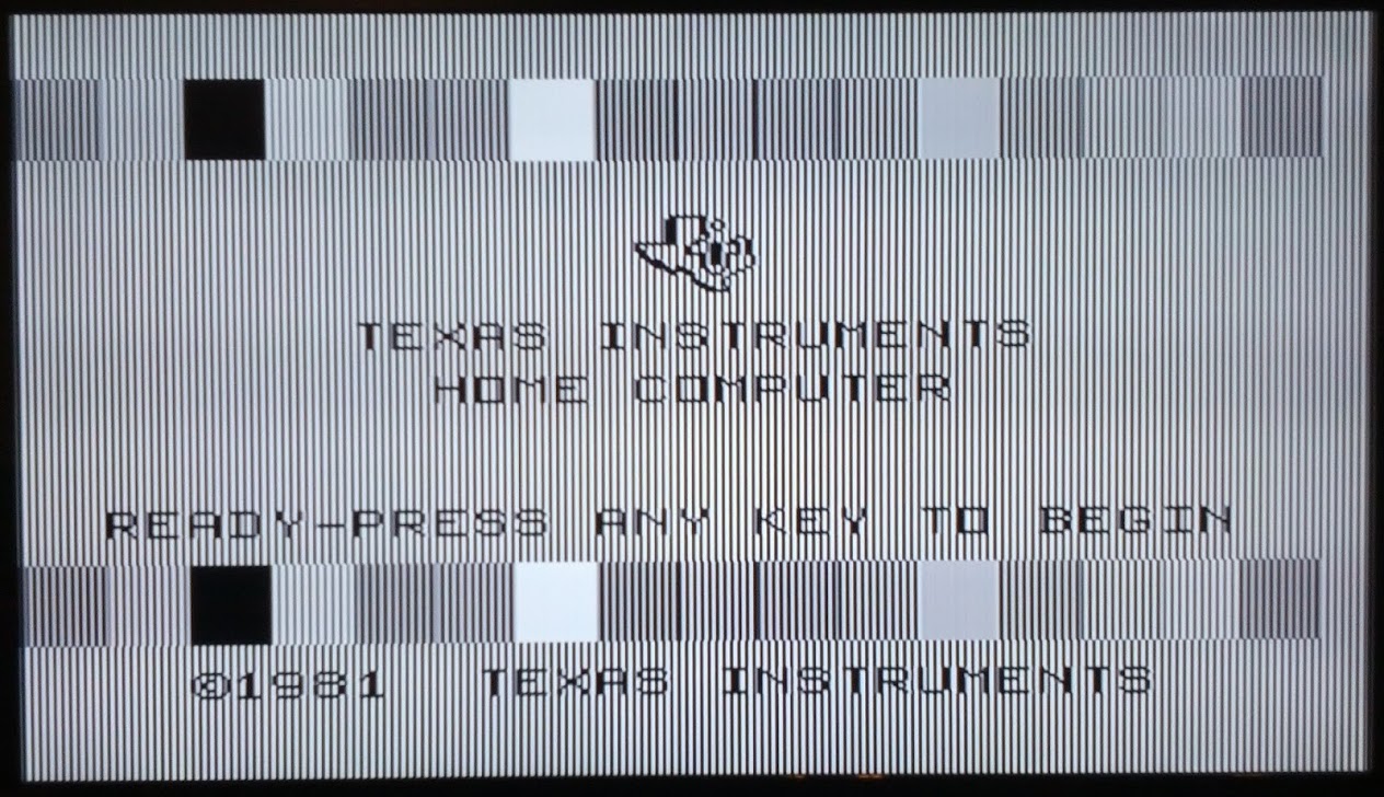
Well, that’s not right! It is in black and white. And what’s with all these vertical black lines? Clearly something’s wrong but what could it be?
New Meets Old
At first I suspected that it was my TV, which is a fairly new LCD. Old computers or game consoles sometimes played a bit fast and loose with the NTSC standard and it seemed unlikely that a new TV would ever have been tested with something as old as a TI-99/4A. Perhaps the TV just couldn’t interpret output from the 99. So I tried with a CRT TV: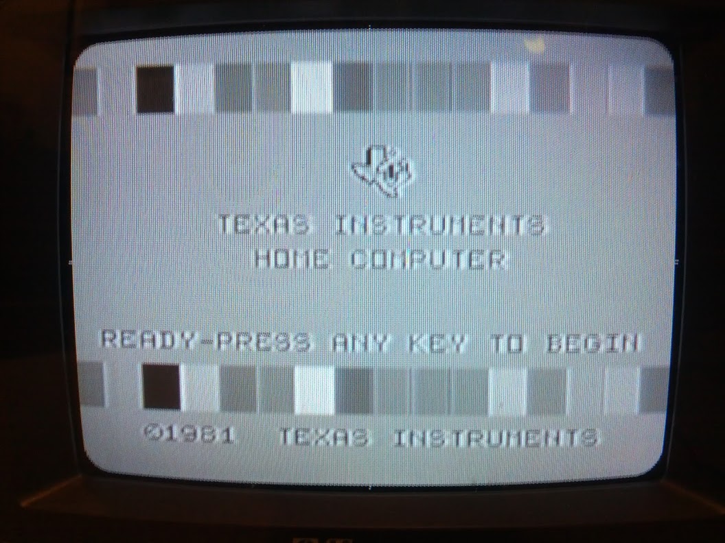
Well the black bars are gone (or at least not as apparent) but it is still in black and white. Something must be wrong with the computer itself.
All About Video Signals
The output from the back of the computer is a composite video signal but using a 5-pin DIN connector (that also carries audio and power) instead of the usual RCA jack. Back when this computer was new that signal would usually to go an RF modulator which was then connected to a TV via a 300-ohm connector. Nowadays you can still do the same thing but since most TVs don’t have screw terminals on the back anymore it can be more convenient to take the composite video signal and hook it directly into the composite input on the TV. All that is required is a simple adapter cable that can be created yourself or purchased online.
I thought that perhaps the video circuitry was generating separate Luminance (Y) and Chrominance (C) signals and then combining them into the final composite output. If this were the case then it would suggest something was wrong in the C amplifier or the final combining stage. It turns out that this is not the case. The video chip in the TI-99/4A is referred to as the Video Display Processor (VDP) and is a TMS9918A, TMS9928A or TMS9929A depending on the region the computer was originally intended for and the television standard in use there (e.g. NTSC or PAL). My computer was made for the US market and outputs NTSC signals using the TMS9918A. This chip has a single video output pin that supplies composite video directly with the Y and C already mixed. So if something was wrong with just the C generation circuitry then it was something broken inside the VDP and my only recourse would be to try to find a replacement chip.
Mad Scientist Equipment
The VDP still seemed to work correctly in all other respects so I was hopeful that the true problem lay elsewhere. I thought I’d take a look at the signal on an oscilloscope. We’d expect to the see the NTSC colorburst and if it was missing that would explain why no color was showing up on the TVs. Here’s what it looked like: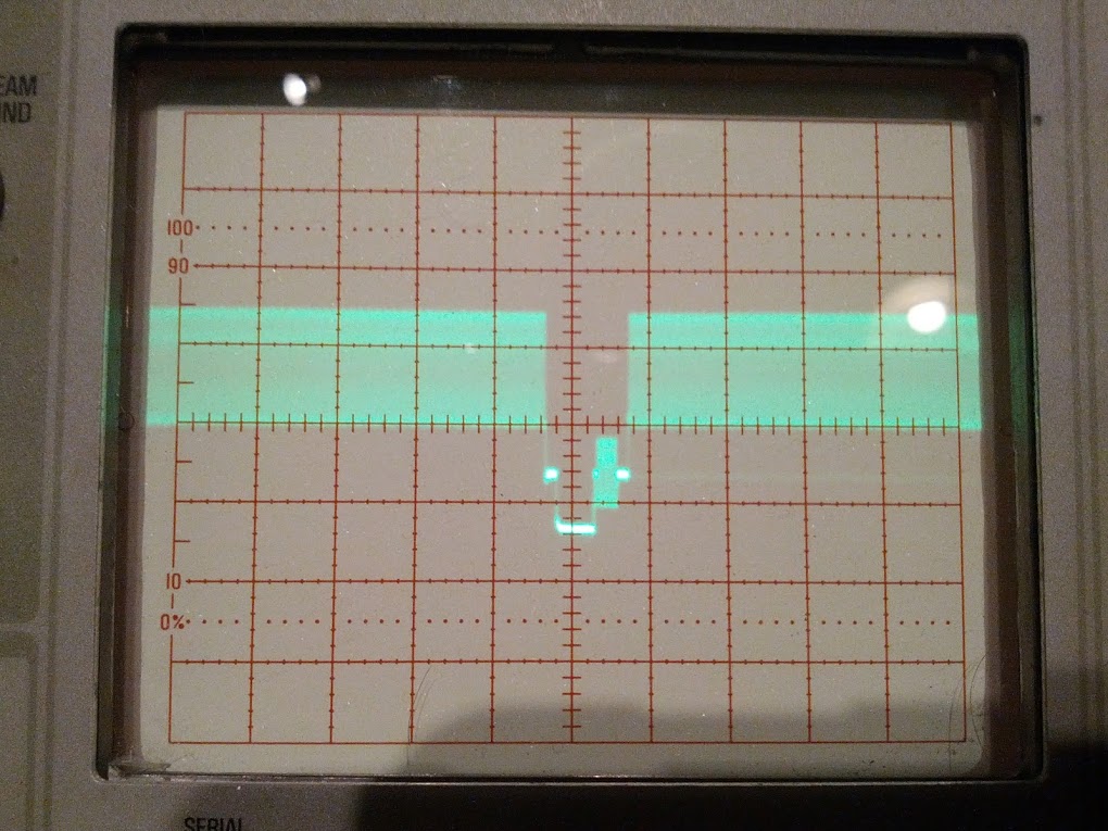
And here’s a closeup of the interesting portion: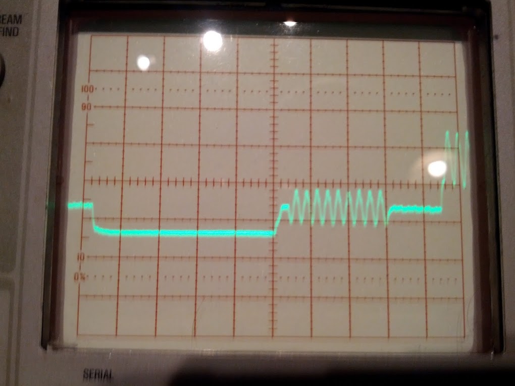
I’m no expert but that looks like a horizontal sync pulse followed by a colorburst to me. But there was still no color on the TV.
The composite video signal that the VDP generates is sent to a simple 2-transistor amplifier and then to the output jack. I didn’t think it was likely but perhaps something in the amplifier had given out and Y was still strong enough to get picked up by the TV but C wasn’t. To test this I took the computer apart and tapped the signal right as it came out of the chip and before it went through the amplifier. It was still black-and-white. This suggested that the problem was not in the amplifier.
The Healing Power of Crystals
At this point I knew that the VDP was mostly working correctly. It generated the right pattern on the screen so it must be able to communicate with both the video RAM and the CPU. That accounts for most of the pins on the VDP, the ones handling digital signals. The remaining pins are mostly for power and the connection to the quartz crystal that provides the timing. I checked the power and that seemed fine. So let’s take a closer look at the crystal: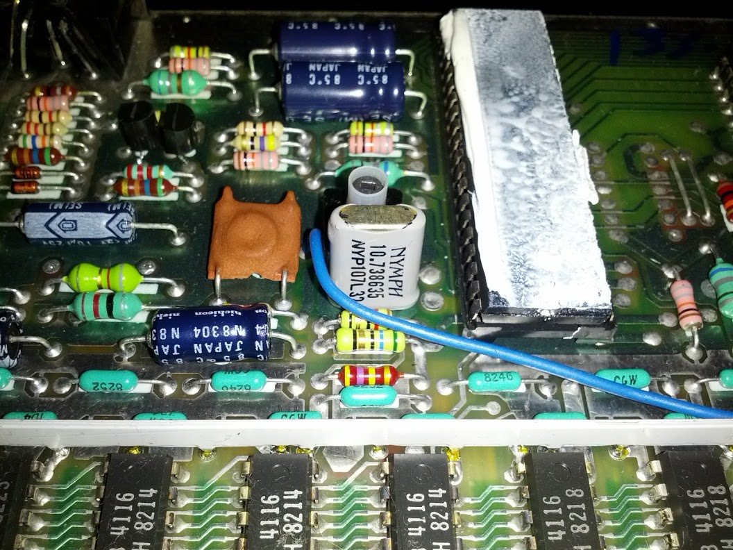
The crystal is the gray-colored component in the middle. To the right is the VDP, covered in thermal paste. Just behind the crystal is a variable inductor.
A variable inductor: now that’s interesting! It is connected to the crystal and apparently used for fine tuning the frequency. Could the fix be as simple as turning an adjustment screw?
Alas, no. I turned it as far as it would go in both directions with no improvement to the video output. If the frequency was off it was beyond the ability of this adjustment to correct. I don’t have any equipment to allow precision measuring of the actual frequency this crystal was producing, but I do have the internet. A little Googling brought me to this post on the TI-99/4A mailing list. Yes, there’s still an active mailing list for a computer that hasn’t been manufactured in almost 30 years!
That post describes the symptoms that I was experiencing and indicated that the solution was to replace the crystal. This was somewhat surprising to me. I’d heard of electrolytic capacitors going bad in old equipment but a quartz crystal? They’re usually quite reliable. But you can’t argue with real-world experience.
The VDP takes the frequency of this crystal (10.738635 MHz) and divides it by 3 to produce the NTSC colorburst frequency (3.579545 MHz). If the frequency of the crystal was off then the generated colorburst would also be off and the TV wouldn’t be able to sync to it. Without seeing a valid colorburst the TV isn’t going to produce any color. That would certainly explain our symptoms!
So after deciding to replace this crystal we have to actually find a replacement part. We want a crystal that runs at exactly 10.738635 MHz. We also need it rated for the proper “load capacitance”. Running a crystal with the wrong capacitance will shift the frequency from the rated frequency. That would be bad since our entire goal is to get the frequency back to the ideal. The original crystal was rated for a load capacitance of 32pF (you can just make out the 32 in the above picture although it is partially obscured by the blue wire). So we want a replacement crystal that’s also rated for 32pF.
Let’s go internet shopping for 10.738635 MHz crystals. Jameco doesn’t carry any. Digikey has some but didn’t have any in stock with a 32pF load capacitance. Luckily Mouser came through for me! A few days later and I had a replacement crystal: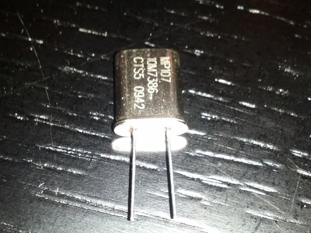
And after a little surgery on the motherboard: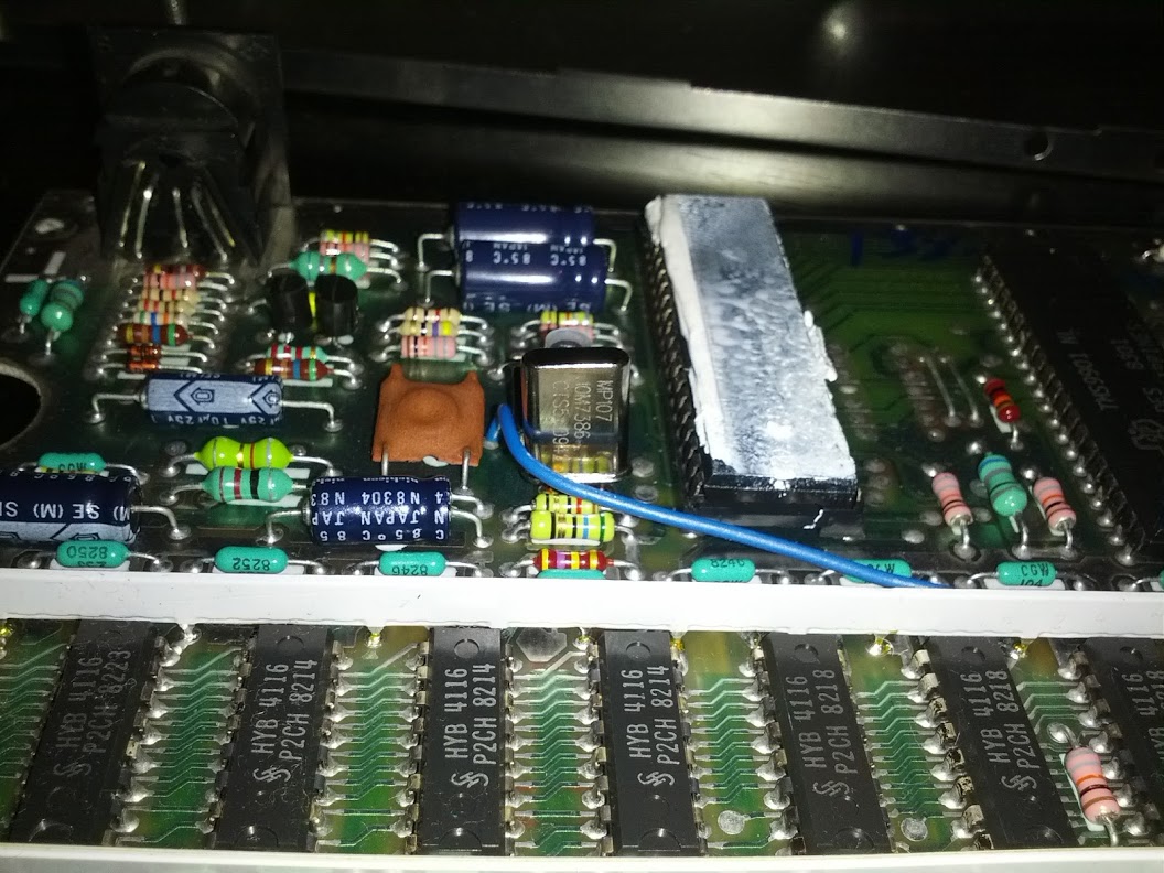
Now for the moment of truth: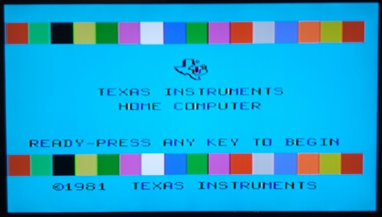
Success! Now to play some Parsec!
Bonus Oscilloscope Image
If you’re wondering what the colorburst looks like with the new crystal then wonder no longer.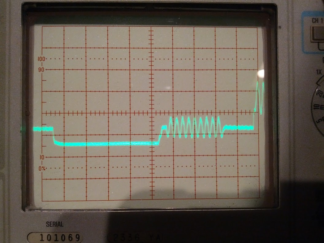
Looks pretty similar to my eyes but apparently it makes a world of difference to a TV.
Obviously !
Nice to see this blog still being active. :-)
Fun technical fact about the VDP implementation:
The TMS9918A VDP actually doesn’t generate separate Y and C directly, from what Karl Guttag told me. It actually generates different phases of the color-burst corresponding to different chroma phases. These are effectively several separate C signals.
It then taps them onto a resistor ladder to get different intensities and in-between phases. So in some sense it’s generating both Y and C together in a combined fashion, since there’s never a distinct ‘C’ signal. The 9918 goes straight to composite.
You can see the actual circuits in figures 10, 11 and 12 of the patent that describes it: http://spatula-city.org/~im14u2c/vdp-99xx/4243984_Video_display_processor_patent.pdf
(The TMS9928A does things a bit differently, and does produce separate Y, B-Y and R-Y signals.)
I’ve had some VDC fun too…
http://www.flickr.com/photos/blakespot/2369732330/in/set-72157604286436870
Wow, without measuring them, those two colorbursts really look practically the same to me. There seems to be a slight shift in its amplitude though, could that have been the problem? Or is it really a minute frequency mismatch that isn’t visible at that scale?
PleasePostMoreOftenPleasePostMoreOftenPleasePostMoreOftenPleasePostMoreOftenPleasePostMoreOftenPleasePostMoreOftenPleasePostMoreOftenPleasePostMoreOftenPleasePostMoreOftenPleasePostMoreOftenPleasePostMoreOftenPleasePostMoreOftenPleasePostMoreOftenPleasePostMoreOftenPleasePostMoreOftenPleasePostMoreOftenPleasePostMoreOftenPleasePostMoreOftenPleasePostMoreOftenPleasePostMoreOftenPleasePostMoreOftenPleasePostMoreOftenPleasePostMoreOftenPleasePostMoreOftenPleasePostMoreOftenPleasePostMoreOftenPleasePostMoreOftenPleasePostMoreOftenPleasePostMoreOftenPleasePostMoreOftenPleasePostMoreOftenPleasePostMoreOftenPleasePostMoreOften.
Seriously though, I’ve loved every single post I ever read here. I would be so happy if you started to post more than once an year!
Ten years or more ago, I picked up an old Amiga that someone had thrown out and it had the same symptom. I wonder if it was the same cause. Seems like of funny that two different pieces of hardware could do something so similar, but then I lack your skill — sorry, I mean Ur Mad SK1LLZ — with the electrons, so I couldn’t fix it and eventually my wife convinced me we needed the space for something useful.
Eric,
Most Amiga models had a monochrome video output and a 23(!) pin socket that carried analogue RGB video. To use a TV or colour composite monitor, you’d plug a modulator into the 23 pin socket. One came in the box with the Amiga 500 (and made the machine even deeper than it already was.)
The Amiga 600 and 1200 had the modulator integrated, and the monochrome video output was replaced with a colour composite output. If that output went bad or you wanted NTSC output on a PAL Amiga (or vice versa) you could still plug in a modulator.
So unless you had an Amiga 600 or 1200, you were never going to see colour as that’s how it was designed. See also Dave Jones in http://www.eevblog.com/2013/03/13/eevblog-438-amiga-500-retro-computer-teardown/ fail to get colour on an old Amiga 500.
You might find my F18A video board an interesting upgrade for your 99/4A. No more worries about failing crystals or DRAM. Also note that there is a very active TI community on the AtariAge forums as well.
Although far less often than with electrolytic capacitors, I have had crystals die on me. I’m glad to see you got your computer working again. And that you made another post :-).
I’m thinking you must have been using variable sweep on that o’scope. Judging by the graticule I don’t see a big enough problem to cause the chroma to completely vanish. I once had an acquaintance bring me an Apple II+ because it had a “vertical rainbow” problem. In other words the overall color shifted in horizontal bands from top to bottom.
One simple fact about older computers: One crystal will source all timing. This guy put a 14 MHz crystal in the motherboard to replace the failed 14.31818 crystal.
The thing is: ALL timing signals will be proportionally incorrect. In the case of my Apple II+ repair, I saw immediately what was wrong just by looking at the screen…. a benefit of spending 10 years troubleshooting broadcast quality video hardware.
In your case I noted all of the timing aspects were correct, approximately 9.5 cycles of colorburst, after a sufficient “front porch” delay after the rising edge of h-sync, which appears in your screenshots to match in both images just as well. Chroma is represented in composite video as a phase and amplitude shift with respect to the colorburst, which is expected to be 3579545 Hz on the nose. The old-fashioned “notch filters” used on older televisions should have sufficiently low Q value to allow the phase shifts to still decode as chroma, so that crystal’s frequency should have been pretty far out of whack. I’m surprised you didn’t have problems with horizontal or vertical “hold” on the older TV on top of the missing chroma since the signal looked okay.
Also of note: the very first screen photo closely resembles that of putting a totally normal signal from your TI into a full-bandwidth composite monochrome monitor. Those types of monitors assume there is no chroma component in the composite signal, and since 3.579545 MHz is very close to the middle range of frequencies used in luma (up to 5MHz defined), the vertical bands you see on the screen are actually the subcarrier peaks being interpreted as very sharp transitions in luma.
I found this article most interesting in the sense that a computer’s master oscillator can be out of spec to a degree where the chroma is not being notched and processed by a composite monitor but is not so far out of whack that the entire video signal is being rejected or too difficult to render on the CRT. The LCD being able to interpret the video anyway makes more sense to me.
Great post! I’ll bear that in mind. Here in the 50 Hz world, the TIs have 6-pin DIN connectors and, alas, no composite output. However, they do have component, i.e. Y, -R-Y and -B-Y outputs. I wonder if that would plug directly into a modern TV’s component inputs? Well, I guess I’ll have to try it.
As for your new LCD screen display, I don’t like the fact that the image is being stretched to fit the width. I’d stick with the original aspect ratio, although that will mean black strips at the left and right. But, draw a circle and it’ll look more like a circle.
Sorry i cant read the oscilloscope (???), so my comments are probably wrong but anyway here goes.
Did the original crystal get faster or slower, or jumpy what exactly went bad with it ? From what i can see the graph seems to be the same exact the rising mountains near the right edge seem to happen earlier.
More new articles! ;) Mooaarh!
Any chance you had a multi-format TV? To see color on PAL TVs, the color burst freq. has to be within +/-50ppm of the target.
IIRC, this was because of how the PAL (multi-format) TVs detected 50Hz VS 60 Hz sources.
Another year has passed without a new article. PLEASE Keep on DOIN’ NEW ONES!
I had same issue, recently. Replacing crystal from Digikey fixed it. What’s interesting is that before I replaced the crystal, going through a RF modulator (which worked fine with two other units that displayed color) gave black and white output. Using a custom cable to direct connect the composite output signal to the TV composite input showed color. So this crystal issue seems to be an interaction with the RF modulator.
Hi Chris,
Did you ever get to the bottom of this?
I have just purchased a couple of 99/4A’s and a composite cable.
I get a crystal clear picture but purely in black & white.
I’m keen to understand what is happening before introducing a soldiering iron to the equation.
If I get colour display using the PAL modulator (everything normal), but Black and White using a direct composite cable into a Samsung LCD TV, does the crystal still need to be replaced or is another solution required?
I love the fact you are gone for a year and back out of nowhere. Keep the articles coming.
I miss my TI-85. Its gotten way too complicated now with the newest versions. Bring back the classics.
Exact same symptoms. Replaced the crystal just like you did. Still b/w image for me. The difference for me might be the fact that I am running the composite video output into a video-to-vga converter box. Then vga to the flat-panel monitor.
I just came across this article about how the Z80’s registers are implemented and it reminded me of Michael Steil’s awesome presentation on the 6502, and hence this site.
http://www.righto.com/2014/10/how-z80s-registers-are-implemented-down.html
Hope we see some updates here again sometime soon. If not, at what point do we need to start making backups of the content here?
Hi blogger, i found this post on 25 spot in google’s search results.
You should decrease your bounce rate in order to
rank in google. This is major ranking factor nowadays.
There is very handy wp plugin which can help you.
Just search in google for:
Sisonum’s Bounce Plugin
James the TI-85 was a classic. Its actually one of the last monochrome screens that Texas Instruments put out in the upper end graphing calculators. After that they switched to a horizontal layout and went to color screens. I agree, the TI-85 was a legend.
Jonathan
Long Live The Internet
I had the very same problem when I revived my old TI-99/4A, and the black and white image with the vertical black lines was so very identical to yours I thought for sure replacing the crystal would fix the problem. I ordered the replacement, put it in with my son a few minutes ago, and boy was I disappointed when the issue remained. Does anyone know of other possible causes? I’m out of my depth here, and I don’t have an oscilloscope to do much digging.
Hey, I’m commenting again for sake of future visitors. I made the previous comment about having the same problem but changing out the crystal not fixing it. In fact, the issue was NEVER with the TI-99/4A in the first place. Apparently, the BenQ computer monitor I was using, which works fine with all its other inputs, can’t cope with an old-school component video signal. I went and bought a cheap TV at Target, connected up the computer, and voila: everything was working perfectly and in color. Problem solved. Yay!
This problem (banded black and white), can also be manifest when attempting to convert the “nearly composite” output to VGA in order to use a monitor. The cheap AV-to-VGA converters commonly available on eBay do NOT interpret the composite signal very well.
However there is an equitable solution to this as well. The cheap up-scaling AV-to-HDMI converters DO work well, and that output can then be piped into a cheap (do get the feeling I’m a stingy cuss?) HDMI-to-VGA converter, if desired.
See: https://atariage.com/forums/topic/233051-using-composite-to-vga-converters/page/2/?tab=comments#comment-3937777