The VIISAN VF3240 is a 2400 dpi A3 flatbed scanner, sold under several names for a few hundred euros. Above 600 dpi, every scan has three defects, coming from the LEDs, from the motor, and from the sensor. vf3240 is an open source driver that talks to the scanner directly over USB and removes them. This article is about the three defects and how they are corrected.
The device
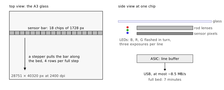
There is a sensor bar under the glass, a little wider than the bed. It is made of 18 chips side by side, with 1728 pixels each, 31104 pixels in all.1 Three LEDs, red, green and blue, are flashed one after the other for every line, so a color line is three exposures. A stepper motor pulls the bar along the bed. An ASIC buffers the lines and sends them over USB, at up to about 8.5 MB/s. A full bed at 8 bit 2400 dpi is 28751 by 40320 pixels and takes seven minutes.
The following figure shows the layout: the bed from above with the sensor bar, and a cross-section of the bar at one chip.
Color fringes and the staircase
Look at this 2400 dpi scan of typeset text with screening dots, enlarged 8x: The left half is the scanner's output, the right half is the corrected version. In the original, every edge has a magenta fringe on its upper side and a green fringe on its lower side, and every four rows look oddly similar.
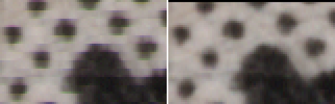
The color fringes come from the LEDs. The three LEDs are flashed one after the other within each line period, blue first, then red, then green, and the carriage keeps moving while they do. So the three exposures of one line see the paper at three slightly different positions, and green sees it furthest along. The three are stored as one row anyway, so the red and blue content ends up a little too low.
The following figure shows this for three rows. The colored dots are the three flashes. The black dot is where the row is drawn, which is where the green flash was.

How far off red and blue are can be measured on a black-and-white page: at 2400 dpi, red is 0.42 rows below green and blue is 0.72 rows below green. This comes from the firmware's timing, so it should be the same on every unit. The fix is to move the red and blue channels back up by that much. At 600 dpi and below, where the carriage moves evenly, they are simply resampled with a Lanczos filter, shifted by these amounts. At 1200 and 2400 dpi the carriage does not move evenly, which is the next defect, so the shift is different for every row, and the two corrections have to be done together.
The staircase
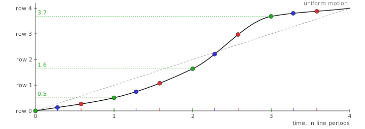
The second defect is in the row spacing. The motor has 600 full steps per inch. At 2400 dpi, one full step is four rows. Within a step, the carriage does not move at a constant speed: it is held in place by friction until the motor's torque is large enough to overcome it, and then it jumps. Yet the four rows are exposed at equal intervals in time. So in practice the four rows of a step sit at about 0, 0.5, 1.6 and 3.7 rows instead of 0, 1, 2 and 3.
The following figure shows the carriage during one motor step, with the twelve exposures. The dashed line is where the carriage would be if it moved evenly. The black curve is where it actually is.
The spacings differ from unit to unit and even drift along the bed during a scan, so the driver measures them from the image itself as it goes. How much two neighboring rows differ tells how far apart they were on the paper. The driver measures this for each of the four rows of a step, which gives the four spacings. Comparing the red and blue channels with green the same way gives their offsets, so at these resolutions the fringe correction is part of this step.
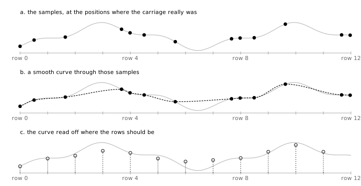
With the spacings known, every row is resampled: a smooth curve is drawn through the samples at their true positions and read off at the position the row should have had. The following figure shows this for one column of pixels. The gray line is the brightness of one channel in that column, across several rows. In the top panel, the dots are the samples where the carriage really was, bunched up and then spread out. The middle panel draws the curve through them. The bottom panel reads it off at the even positions the rows should have had.
After the correction, the rows are evenly spaced and the colors line up. The rows that fall into the big jump stay a little softer than the others: the paper there was never looked at closely, and what was not recorded cannot be recovered.
Seams
A sensor this wide is built from 18 chips, and the chips do not meet exactly. At every junction, a few pixels are missing. So everything to the right of a junction is drawn too far to the left, and every line that crosses it has a kink. The following figure shows the 18 chips with the gaps between them and the vertical offsets described below, both exaggerated.

The following picture shows a halftone screen across a chip junction at 2400 dpi, enlarged 4×. On the left, as scanned, the rows of dots jump sideways at the seam. On the right, corrected.

The gaps are three to five pixels wide, and they differ from chip to chip and from unit to unit, so they have to be measured. The ruler is a printed page of dots: the dots form a regular grid, and right of a seam the whole grid is drawn too far to the left, by exactly the width of the gap. The same measurement shows that the chips are also offset vertically by a fraction of a row each, about 12 rows across the whole bar. The driver comes with a printable target and a calibration mode for this. Without a calibration, it falls back to four pixels per seam and warns about it at every scan.
To correct the seams, each row is stretched so that the missing pixels are filled in, and the columns of each chip are moved up or down by that chip's offset. What remains is a fraction of a pixel.
The driver
The vendor's driver leaves all three defects as they are. The protocol was recovered from the vendor's Linux driver and written up as a specification, and the code was written from that. The driver supports all resolutions from 200 to 2400 dpi, color and gray, 8 and 16 bit, any area of the bed, and scanning on the front-panel buttons.
cargo build --release
vf3240 page.tif --dpi 2400
vf3240 --seam-target target.pdf    # print, lay on the bed, then:
vf3240 --calibrate-seams
Source and documentation: github.com/mist64/vf3240.
-
Only 28751 of them look at the bed, so the first chip and part of the second lie outside the image, and 16 of the 17 junctions are inside.↩
0 thoughts on “Correcting a 2400 dpi A3 Scanner in Software”