The user port of the Commodore 64 exposes a TTL-level RS-232 serial port that supports up to 1200 baud1. In 1997, Daniel Dallmann came up with a very sophisticated trick that allowed sending and receiving at 9600 baud2, using slightly different wiring and a dedicated driver. This “UP9600” wiring has become the de-facto standard for all modern accessories, like C64 WiFi modems. Let’s see how UP9600 works.
History
Before diving into the details of RS-232 and the UP9600 solution, let’s look at some historical context.
MOS 6551 ACIA
MOS made an RS-232 chip for the 6502: the 6551 ACIA (“Asynchronous Communications Interface Adapter”), which, per specification, can support up to 19200 baud. Commodore used it in the SuperPET (1981), the CBM-II series (1982) as well as the business-oriented Plus/4 (1984). It is exposed through a KERNAL driver as device #2.
6551 Emulator
For cost saving reasons, the VIC-20 and its successors, the C64 and C1283, did not contain a 6551 chip. Instead, Commodore included a bit-banging driver in the KERNAL that emulated the 6551 and exposed it as device #2. This emulator supports up to 2400 baud, but due to DMA from the VIC-II video chip (“badlines”), only speeds up to 1200 are stable on the C64 (and the C128 in 40 columns mode).
Software 2400 baud
In the article “Toward 2400” in Transactor volume 9, issue 3 (Feburary 1989), George Hug presented software to achieve 2400 baud reliably on the C64 without any hardware modifications4.
SwiftLink-232
The primary use for RS-232 on the C64 was for modems, and as modems faster than 2400 baud became available, Dr. Evil Laboratories released the $30 SwiftLink-232 cartridge for the C64 expansion port in 1990. It contained a 6551 chip that could even reach 38400 baud, thanks to doubling the rate of the external oscillator.
UP9600
In 1997, Daniel Dallmann created UP9600, a solution that allowed 9600 baud on the user port. The idea is to use the hardware shift registers of the two CIA 6526 I/O controllers to do the timing-critical part of the transfer.
RS-232 Pins on the User Port
Every Commodore 8 bit computer except for the C16/C116 has a user port, and all user ports except for the original PET support TTL-level RS-232 through eight dedicated pins.
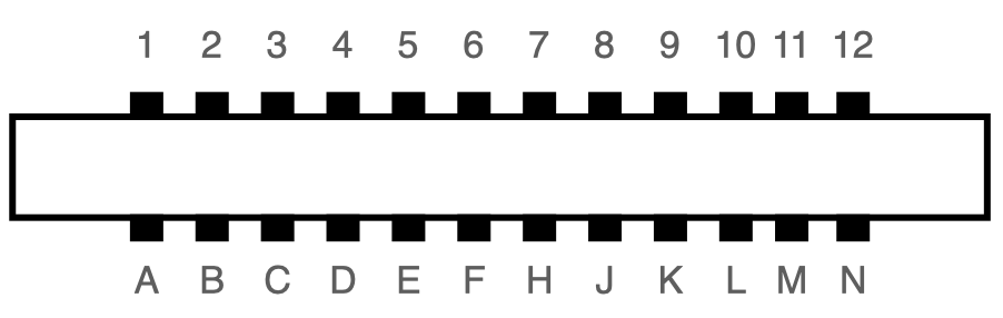
The following table describes the C64 user port. The RS-232 pins are marked in red:
| Pin | Description | Pin | Description |
|---|---|---|---|
| 1 | GND | A | GND |
| 2 | +5V | B | /FLAG2 |
| 3 | /RESET | C | PB0: RS-232 RXD ⬅ |
| 4 | CNT1 | D | PB1: RS-232 RTS |
| 5 | SP1 | E | PB2: RS-232 DTR |
| 6 | CNT2 | F | PB3: RS-232 RI |
| 7 | SP2 | H | PB4: RS-232 DCD |
| 8 | /PC2 | J | PB5 |
| 9 | SER ATN IN | K | PB6: RS-232 CTS |
| 10 | 9 VAC | L | PB7: RS-232 DSR |
| 11 | 9 VAC | M | PA2: RS-232 TXD ⬅ |
| 12 | GND | N | GND |
RXD is the receive line, and TXD is the transmit line. The remaining lines deal with flow control, among other things, and are optional.
RS-232
Before we can talk about UP9600, we first need some understanding of the RS-232 serial protocol.
To send serial data from one sender to one receiver, only a single data wire is needed. Beforehand, the two devices need to agree on the baudrate (e.g. 1200 bits/sec) and the format of each unit of data: how many data bits, whether there is an added parity bit, and how many stop bits. The most common parameter setting (and in fact the only one supported by the original UP9600 driver) is 8-N-1, meaning 8 data bits, no parity, and a single stop bit.
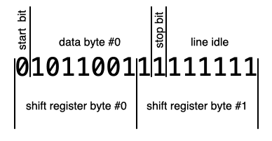
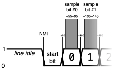
The transmission of one byte in 8-N-1 mode will look like this on the wire:
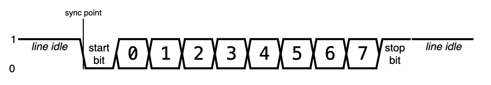
- “1” on the wire signals an idle line: the sender has no new data to send.
- The transmission of a byte is indicated by sending a “0” for the duration of one bit.
- The 8 data bits are transmitted afterwards, LSB first.
- After that, a “1” is sent for at least the duration of one bit.
- If there is no additional data, the line stays at “1”.
Data can be sent back to back if there are multiple bytes available for sending:
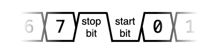
As usual, the 8 data bits are followed by a stop bit (“1”), then immediately by a start bit (“0”) and then the next 8 data bits.
The point in time when the sender sets the wire from “1” to “0” for the start bit is the synchronization point for the transmission of the following byte. The receiver will have to sample the line at the right intervals counting from the sync point for the following 8 data bits and the stop bit. The next start bit will re-sync sender and receiver again, so the clocks of sender and receiver only have to be matching well enough for the duration of the transmission of a single byte.
After the line has been idle, a start bit can be sent at any time, it does not have to fall into the time raster of the bit rate. As just described, time starts anew with each start bit for both sender and receiver.
If the receiver starts listening while the sender is already in the middle of a transmission, incorrect data will be received. The first “0” bit it encounters will be understood as the start bit, and the next 8 bits will be the data byte. If the following bit is not a “1”, the receiver will discard the byte, and wait for the next “0” bit, which hopefully is the correct start bit this time. In the worst case, it will detect a few garbled bytes, but statistically, the receiver will sync itself over time.
The CIA 6526 Shift Register
The core idea of UP9600 is to use the two otherwise unused hardware shift registers in the C64, which can automatically send or receive a byte bit-by-bit over a single wire, faster than the CPU would be able to do it.
The C64 has two CIA 6526 I/O controllers, each of which contains a serial shift register that can transfer bytes using a clock and a data line to a peer that speaks the same protocol, e.g. the CIA in another computer5. They are unused by a stock C64, but exposed on the user port. Here is the table again, this time with the shift register wires marked in red:
| Pin | Description | Pin | Description |
|---|---|---|---|
| 1 | GND | A | GND |
| 2 | +5V | B | /FLAG2 |
| 3 | /RESET | C | PB0 |
| 4 | CNT1 | D | PB1 |
| 5 | SP1 | E | PB2 |
| 6 | CNT2 | F | PB3 |
| 7 | SP2 | H | PB4 |
| 8 | /PC2 | J | PB5 |
| 9 | SER ATN IN | K | PB6 |
| 10 | 9 VAC | L | PB7 |
| 11 | 9 VAC | M | PA2 |
| 12 | GND | N | GND |
CNT1 and SP1 are the clock and data lines of CIA#1, and CNT2 and SP2 are the clock and data lines of CIA#2.
In order to send a byte, we need to set timer A so it fires at the correct interval between bits6
timer = (system_freq) / (2 * bit_output_freq) - 1
and set it to continuous mode, set the serial port to output, and then write the byte to the serial data register. On every timer underflow, the CNT line will be toggled, and on every falling edge, the next bit is put on the SP line – this is why the timer has to fire twice per bit, explaining the extra factor of 2 in the divisor of the formula.
Once all 8 bits are shifted out, a bit in the interrupt control register is sent, which can optionally trigger an interrupt. The SP line will retain the value of the last bit.
To send a continuous stream of bytes, you have to write the first two bytes to the serial data register immediately after one another – the CIA will start sending out the first byte and cache the second one – and after each interrupt, a new byte can be written to the shift register, while the previous one is still being shifted out.
To receive a byte through the shift register, you have to set it to input mode, and it will sample a bit on every rising edge of CNT. Again, after 8 bits, it will set a bit in the interrupt control register and optionally trigger an interrupt. Now, the 8 bits can be read from the serial data register.
CIA#1 and CIA#2
The two 6526 CIA chips in the C64 are identical, but connected differently.
- Most pins of the user port, and all RS-232 pins go to CIA#2.
- The serial ports of both CIAs are exposed on the user port.
- The interrupt output of CIA#1 is connected to the CPU’s IRQ line, while the interrupt output of CIA#2 is connected to the CPU’s NMI line.
Receiving data is more timing-critical than sending, so we will use CIA#2 for receiving, since NMIs are useful for tighter timing requirements.
Sending RS-232 Data
Now how do we use the shift register to send data in the RS-232 transmission format? After all, it was not exactly designed with RS-232 in mind:
- The user port wiring of the serial port is different than what the KERNAL driver uses.
- The order of the bits in a byte is reversed in the CIA compared to RS-232.
- The shift register works on 8 bits at a time, while RS-232 deals with groups of 10 bits.
TXD Wiring
The data output of the CIA#1 shift register is wired to SP1 (pin 5) on the user port, but the old RS-232 KERNAL driver outputs data on PA2 (pin M). This means that existing user port RS-232 hardware (which uses pin M) wouldn’t be compatible. But new hardware that is aware of UP9600 can just bridge pin M to pin 5, and it will be compatible both with the original pinout and with UP9600.
The additional clock output of the CIA is not a problem: It will appear at pin 4 (CNT1) on the user port, and existing user port RS-232 hardware wouldn’t have it connected, and there is no reason to connect it on new hardware.
Bit Order
The shift register sends data with the most significant bit first, while RS-232 sends the least significant bit first. The 8 data bits will have to be reversed in order before sending them. The fastest solution is a 256 byte lookup table. The UP9600 code actually uses a 128 byte lookup table and patches the remaining bit into the resulting byte, trading some execution speed for memory.
Sending 10 Bits
The trickiest problem in sending is that the shift register works on 8 bits at a time, while for RS-232, each data byte results in a total of 10 bits: one start bit, 8 data bits and one stop bit. If all the data to be sent were known beforehand, one could shift the data bytes into a set of bytes that corresponds to the RS-232 bit stream and continuously write them to the shift register:
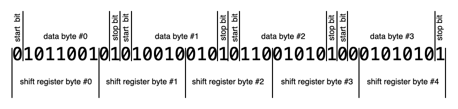
Unfortunately, software that wishes to send data often doesn’t have all the data available, or data arrives from software in bursts with pauses in between. In a terminal program, text typed by the user arrives one byte at a time, with significant pauses. During file transmission (e.g. XMODEM), a number of bytes will be sent together, but without additional communication, the RS-232 driver wouldn’t know at what point it needs to flush the accumulated data. It’s possible to do it this way, but it is quite complicated.
Instead, the UP9600 software sends every data byte as 16 bits, the 10 RS-232 bits (one stop bit, 8 data bits, one stop bit), and 6 filler bits with a value of “1” – you can see them either as additional stop bits or as a signal that the line is idle.
While this only achieves 62.5% of the peak data rate – 600 bytes/sec instead of 960 bytes/sec, assuming 9600 baud – this is completely legal and will be understood by any receiver. It does not look any different than a sender that had to add a little extra pause between bytes.
So in practice, the UP9600 code always sends one data byte at a time, like this (using CIA#1):
- Set the serial port to output.
- Enable serial port interrupts.
- Set timer A to 1022727 / (2 * 9600) – 1 = 52 (NTSC) or 985249 / (2 * 9600) – 1 = 50 (PAL)7.
- Set the timer to continuous and start it.
- Write a “0” (start bit) and bits 0 through 6 to the serial data register – note the reversed bit order!
- Write the remaining bit and seven “1” bits (stop bits) to the serial data register. Again, note the bit order.
The next byte can be written once two interrupts have been triggered by the CIA.
(There is a little added complication: Serial timing has to come from the timer A, but the C64 KERNAL has timer A of CIA#1 set up as the 60 Hz interrupt source that deals with updating the TI$ clock, scanning the keyboard and blinking the cursor. We have to migrate the 60 Hz interrupt to timer B if we want to continue using these KERNAL services.)
Let’s look at the timing of this code: We have to make sure that the second byte is written before the first byte is fully transmitted. Otherwise, the last bit of the first byte (i.e. second-to-last data bit) would stay on the line too long, leading to incorrect data transmission. With 9600 baud, we have a window of about 100 clock cycles.
- Every 8 raster lines, the VIC-II takes control from the CPU for 40 cycles (“badlines”).
- We could be interrupted by an NMI caused by the receiving part of the UP9600 software – see below.
As long as the receiver NMI code takes less than 60 cycles, we’re good at 9600 baud, even when a badline and an NMI occur at the same time. In fact, even higher speeds could be possible by avoiding VIC-II badlines – after all, we control when to start the transmission of a byte. But since the baud rate is the same for sending and receiving, it’ll be the receiving part that will limit the maximum bit rate.
Receiving RS-232 Data
Receiving is also tricky because:
- Again, the user port wiring of the serial port is different than what the KERNAL driver uses.
- A start bit and thus the transmission of a data byte can happen at any time, and at 9600 baud, the window for a single bit is just 100 cycles.
- The shift register has no way to shift in a bit every n cycles.
RXD Wiring
The data input of the CIA#2 shift register is wired to SP2 (pin 7) on the user port, but the old RS-232 KERNAL driver receives data on PB0 (pin C). As with the output wire, new hardware that is aware of UP9600 can just bridge pin C to pin 7 and be compatible with both drivers.
Detecting the Start Bit
To detect a start bit, we have the following options:
- Busy waiting. This way, there will be no way to do anything else on the system.
- A timer interrupt that fires every 100 cycles, so we can check the line. This would be a lot of interrupts, slowing down the system significantly.
- Finding a way to have the stop bit cause an interrupt.
In fact, it is possible to have an external pin on the user port generate an interrupt – a falling edge on FLAG2 (pin B) will make CIA#2 trigger an NMI. So UP9600-aware hardware needs to bridge PB0 (pin C), which normally carries RDX (receive line) to FLAG2 (pin B).
The UP9600 software thus enables the FLAG interrupt on CIA#2 and hooks the NMI vector. Once the NMI fires, it sets up the CIA#2 to read the next 8 bits into the shift register.
Using a CIA Timer for the Clock
The trickiest problem in receiving is the fact that for data input, the shift register has to be clocked from the CNT line, and we don’t have such a signal! There is no way to tell the shift register to just sample the data wire every n clock cycles.
The trick is to have the CIA generate a matching clock signal, output it on the user port, and use a bridge on the UP9600-aware device to feed this signal back into the CIA through the CNT2 pin.
The CIA has a way to send a pulse every n cycles on pins PB6 and PB7. When enabled, an underflow of timer A will pulse PB6, and an underflow of timer B will pulse PB7. And both these CIA outputs are available on the user port! UP9600 uses timer B for this, so we need a bridge from PB7 (pin L) to CNT2 (pin 6).
So inside the NMI handler for the start bit, we have to
- Disable FLAG interrupts – we are not listening for a start bit any more.
- Set the serial port to input
- Enable serial port interrupts.
- Set timer B to 1022727 / (9600) – 1 = 106 (NTSC) or 985249 / (9600) – 1 = 102 (PAL).
- Set the timer to continuous, set it to pulse on PB7 and start it.
- Change the NMI vector to the second NMI handler.
The second NMI handler will then
- Read the data byte from the serial data register and reverse the bit order.
- Disable timer B.
- Enable FLAG interrupts for the next start bit.
- Change the NMI vector to the first NMI handler.
Note that we never read the stop bit. This means that the UP9600 does not plausibility check of the data. If the receiver starts listening while the sender is already in the middle of a transmission, the UP9600 driver will pass several garbled bytes to the receiving software and take longer than necessary to eventually sync itself to the signal.
UP9600 Wiring
So for a C64 user port RS-232 device to be UP9600-aware, all it needs to do is bridge the following pins:
| Pin 1 | Pin 2 | Description |
|---|---|---|
| M (PA2) | 5 (SP1) | RS-232 output to CIA#1 Serial Port |
| C (PB0) | 7 (SP2) | RS-232 input to CIA#2 Serial Port |
| C (PB0) | B (/FLAG2) | RS-232 input to CIA#2 FLAG, for NMI on start bit |
| L (PB7) | 6 (CNT2) | CIA#2 timer B pulse to CIA#2 Serial Port clock |
UP9600 does not work on a C128 in 128 mode, since it uses the CIA#1 shift register for communication with Fast Serial disk drives (1571, 1581, …). It will even hang on boot if a Fast Serial device is attached. To work around the latter, a jumper can be installed to disconnect M from 5.
Why is 9600 the Maximum Baudrate?
The highest baudrate that is possible on a C64 with the described algorithm is 9600 baud.
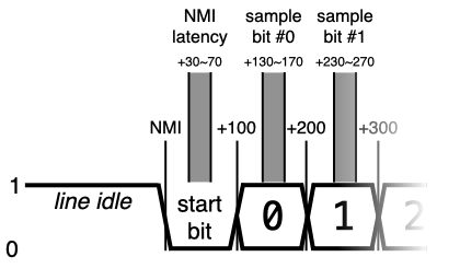
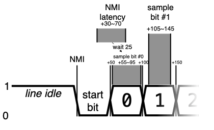
At this speed, a bit arrives roughly every 100 cycles. It takes about 30 cycles from the moment of the start bit NMI to disable the FLAG NMI, enable the timer and hook the serial port NMI. 50 cycles after the start bit NMI would be the center of the start bit and the optimal time to sample every 100 cycles, so starting the timer 30 cycles into the start bit is fine.
The interesting part on the C64 are VIC-II badlines, which can stall the CPU for 40 cycles at practically any time. If a badline happens just as the NMI is taken, setting up the CIA to read the 8 data bits will be finished 40 cycles later, i.e. at 70 cycles after the moment of the start bit NMI. This is still fine, because in either case, we will fall into the window where the start bit is valid.
The next highest standard baudrate would be 19200, with a bit every 50 cycles. With the same algorithm, the following will happen: If there is no badline, we will set up the CIA at 30 cycles again, and it will sample every 50 cycles, so pretty much in the center of each bit. Great. But if there is a badline, we’re already at 70 cycles, which is in the middle of the first data bit. The first bit would have to be read by the serial port immediately, 50 cycles later would be too late.
We can’t detect whether a badline just happened, but since the window to read a bit is 50 cycles and the fuzz introduced by badlines is just 40 cycles, we have a chance to time it just right to read the bit within the window.
Depending on whether there is a badline, the latency from the moment of the start bit NMI to the point where we can access the CIA is 30 to 70 cycles. The process would be to:
- Wait 25 cycles, so we fall into the 55 to 95 cycle range, in the center of the window of bit #0. These cycles can be used to set up the shift register and disable the FLAG NMI.
- Output a manual pulse on PB7 to sample the first bit into the shift register immediately.
- Set up the timer to pulse PB7 every 50 cycles and start it.
The implementation of UP19200 is left as an exercise to the reader.
Source Code
- The original UP9600 source code is available as part of an email from Daniel Dallmann to the developer of Novaterm, dated 30 Nov 1997. It is designed as a library that can be used from BASIC or assembly.
- Bo Zimmerman maintains a version of UP9600 as part of the ZiModem repository that hooks itself into the KERNAL vectors for the Channel I/O calls, so UP9600 can be used from BASIC or assembly using the existing KERNAL interface.
- The CCGMS terminal program contains a version adapted by alwyz. It is the only version to also support, in addition to 9600, baudrates of 300, 1200, 2400 and 4800. The current version in the repository contains fixes, cleanpus and comments by myself.
Related
- over5 by Daniel Kahlin can do 38400/8N2 with the screen off.
- Retroterm (CSDb) by Jorge Castillo can do 57600/8N1 with the screen off, and – using RTS/CTS flow control – an effective throughput of 1500 (PAL) or 1800 (NTSC) baud equivalent by only receiving in the border area.
-
It is supposed to support 2400 baud as well, but this speed does not work reliably in practice. ↩
-
Sending won’t achieve the full data rate though; we’ll cover this in the article. ↩
-
Development machines of the C128 did contain a 6551. ↩
-
A modern version of this software exists in the form of a cc65 driver. ↩
-
This is the same shift register that was supported, but broken in the MOS 6522 VIA chip, which is why the 1541 disk drive was so slow. ↩
-
The timer value has to be one less than the quotient, because in continuous mode, automatic reloading of the timer takes one extra cycle. ↩
-
1022727 and 985249 are approximations of the respective system clock rates in Hz. The exact numbers are 4/14 * 315/88 for PAL and 4/18 * 4433618.75 for NTSC. The two constants are the respective colorbust frequencies.↩
Great article.
I wonder why WIFI modems even go through the hassle of serial communications.
If I understood this article correctly there are 9 freely usable GPIO lines plus an interrupt input. One could use 4 bits of data, plus 5 control bits, with perhaps one for data direction, one strobe, one ack and one to check if there is data to be read. The WIFI interface could send an interrupt if it has new data, or get an interrupt when the strobe line is asserted. Of course you’d need bidirectional level shifters.
Hmm I need to think about this some more. Maybe there is even a simple symmetrical way to transmit and receive data without changing pin directions.
WiC64 (https://www.wic64.de) does something like this. It uses one GPIO, controlled by the C64, to indicate the data direction, 8 GPIOs for bidirectional data transfer, and another GPIO, written to by the hardware, to indicate the hardware has either accepted the byte or has a byte ready.
Hi Christian:
The answer to your question is this: Compatibility with decades of software.
Thank you for this article! Two years ago, when I was working on a userport serial adapter for a microcontroller board, I wasn’t able to find such detailed information about this. In the end, I only used my board at 2400 baud anyhow.
Great read. I wish 31250 baud were possible on the user port so I could control the SID with a MIDI controller but it seems like the expansion port cartridge is still the only way. I have an arduino uno hooked up to a breadboard with a midi circuit and user port but the mismatched baud rates cause the C64 to read junk.
Thanks, didn’t know about this.
As a side track, the 6551 can also reliably do 115200bps with the standard clock oscillator. The Commodore Amiga A2232 seven port serial interface board uses a version of the 6502 CPU, seven 6551 chips, a bunch of static ram chip and some I/O and glue logic to make the ram readable and writeable both from the 6502 and the computers main 68k processor and also to start/stop/reset the 6502. When the Amiga driver is loaded it transfers code to the board and starts the 6502 CPU. The original driver supplied with the board could only handle 19200 with the default clock and if you changed the crystal oscillator you could get 38400 on at least one port. However in the 1990’s an alternate driver was developed and uploaded to Aminet and that driver can reliably do 115200 bps on two of the ports at the same time, and also as a bonus with unnoticeable CPU load on the Amiga side as the A2232 card has enough ram to buffer enough data that card interrupts isn’t needed so the Amiga side of this better driver polls the card during the vertical sync interrupt that anyways will always run, and if there is any data to transfer it can do it as a block.
Btw, as you mention there are bugs in the 6522 serial ports. Afaik those appear if the clock isn’t perfectly synchronized with the cpu/system bus clock. This makes me think that by accessing these serial interfaces on a VIC 20 (or for that sake on a 1541) it could be possible to not only do the same thing on that computer, but also at higher speeds as there are no bad line with it’s lower resolution.
Also, is the text correct re Retroterm? I would assume that it would only use hardware handshake for the actual badlines and receive/transmit during the visible parts of the non-badlines?
I loves me some good C64 RS-232 articles. I just posted my own take on the topic over on my own blog.
Anyway, worth mentioning in your Related section is İlker Fıçıcılar’s tighter bit-banging algorithm. I ported it for some GEOS terminals and got a clean reliable 4800bps. My port struggles at 7200, but Ilker claims he can do 9600.
http://cbm.ficicilar.name.tr/program/7/rs232-communication-library
There’s a small typo in the article. “(one stop bit, 8 data bits, one stop bit)”. Obviously that is meant to say “(one start bit, …”.
Footnote #7 has “for PAL” and “for NTSC” reversed, I believe. The 4/18 * 4433618.75 formula gives the speed for PAL not for NTSC, and vice versa.