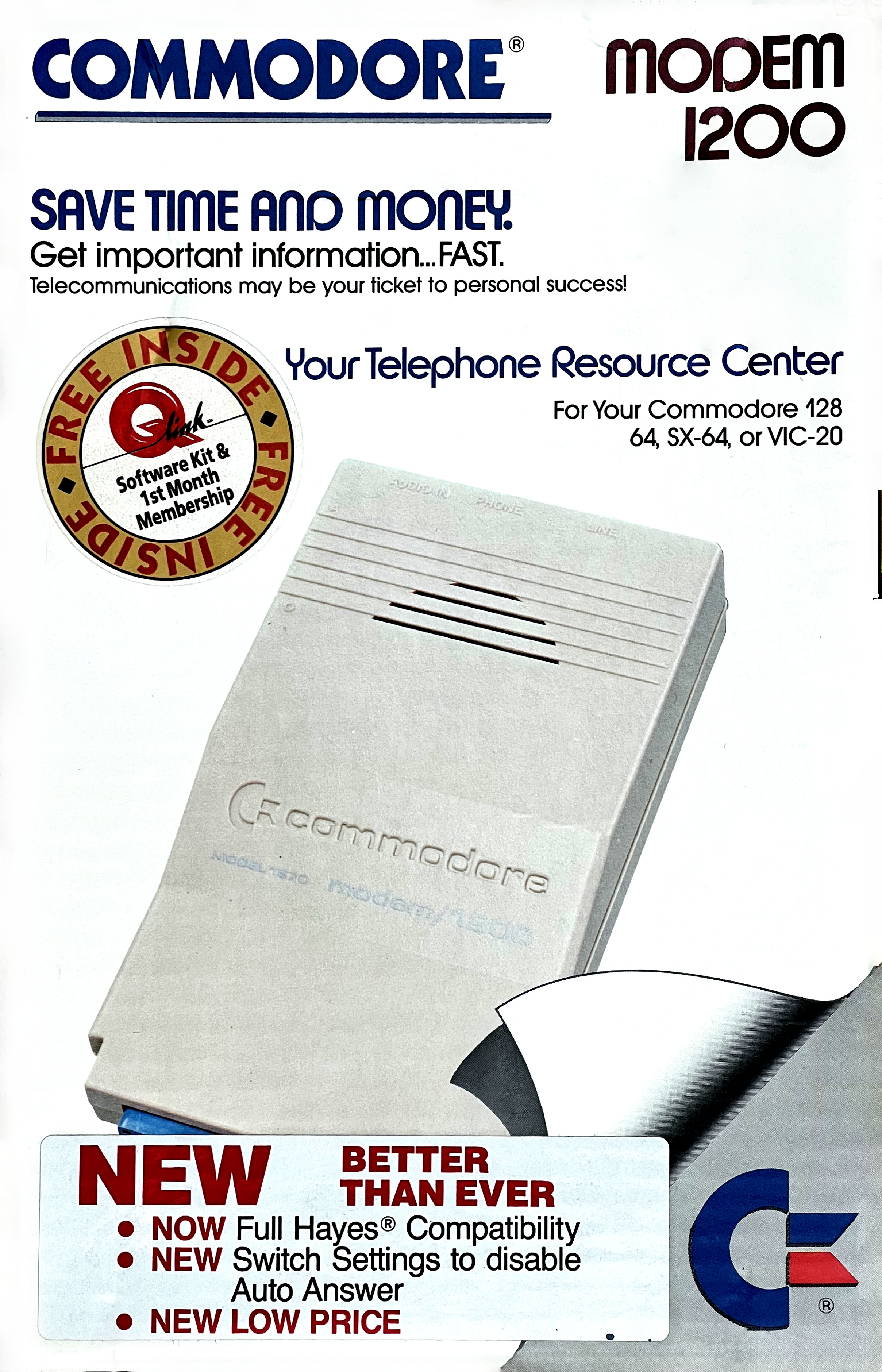
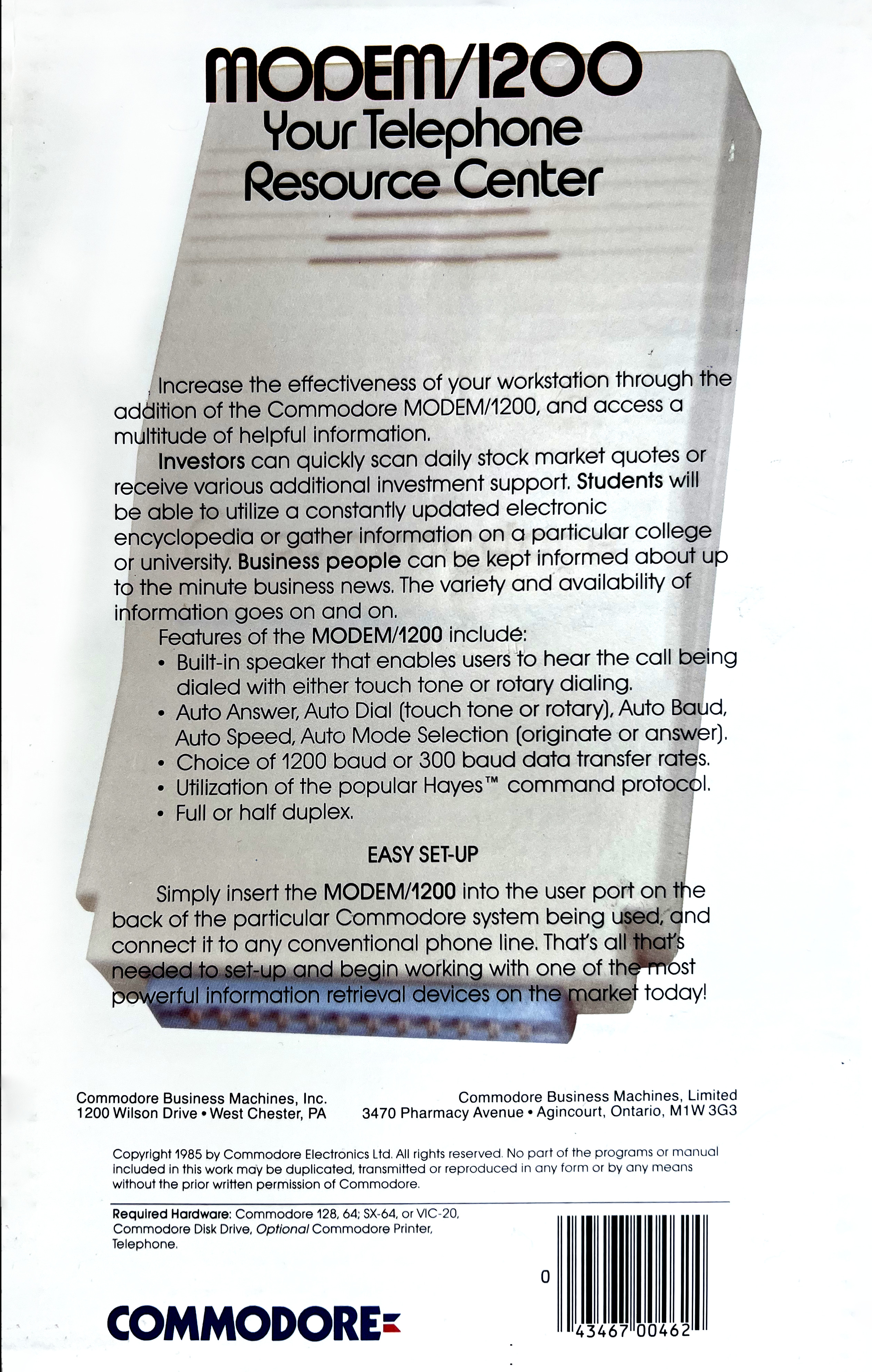
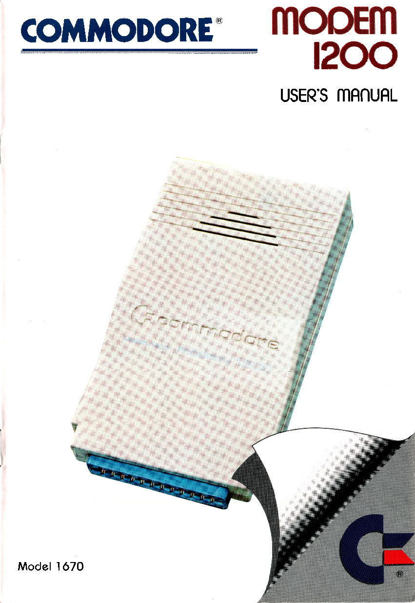
The Commodore 1670, also known as the “Modem/1200”, is Commodore’s first Hayes-compatible modem: It connects directly to the phone line and supports pulse and tone dialing for 1200 and 300 baud duplex connections. There were two revisions, the original 1670 and the “new” 1670, a.k.a. CR-1670. (The unit in this article is the later revision.)
Historical Context
| Year | Name | Model | Description |
|---|---|---|---|
| 1982 | VICMODEM | 1600 | connected to phone’s handset connector; manual dialing through phone; Motorola MC14412 |
| 1982 | AUTOMODEM | 1650 | connected to phone line, pulse dialing in software; Motorola MC14412 |
| 1985 | MODEM/300 | 1660 | added tone dialing support by feeding SID output into modem; Texas Instruments TMS99532A |
| 1987 | MODEM/1200 | 1670 | Hayes command set; pulse and tone dialing in hardware; 300/1200 baud support; U.S. Robotics chipset |
Photos
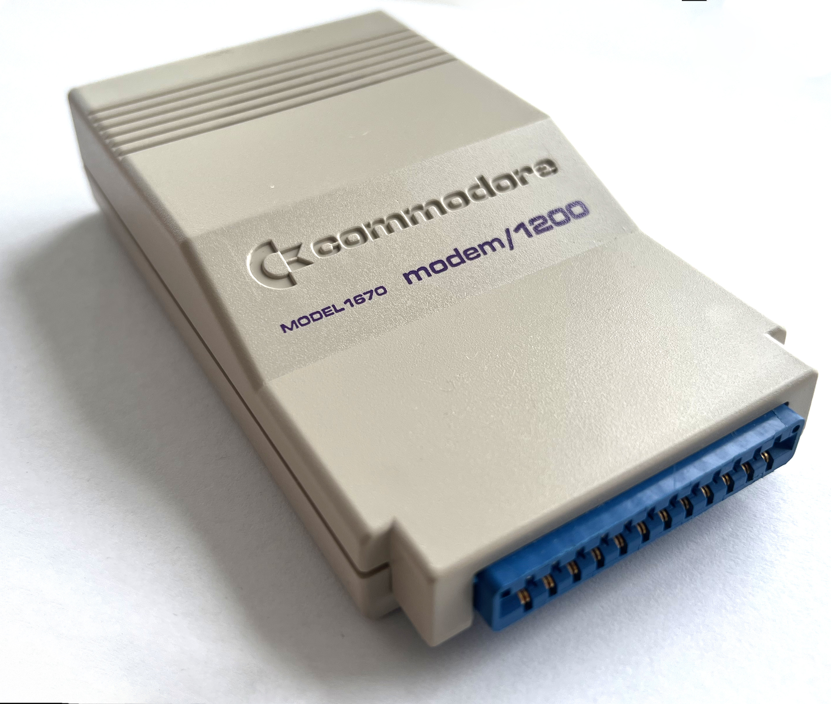
On the front, there is the user port connector.
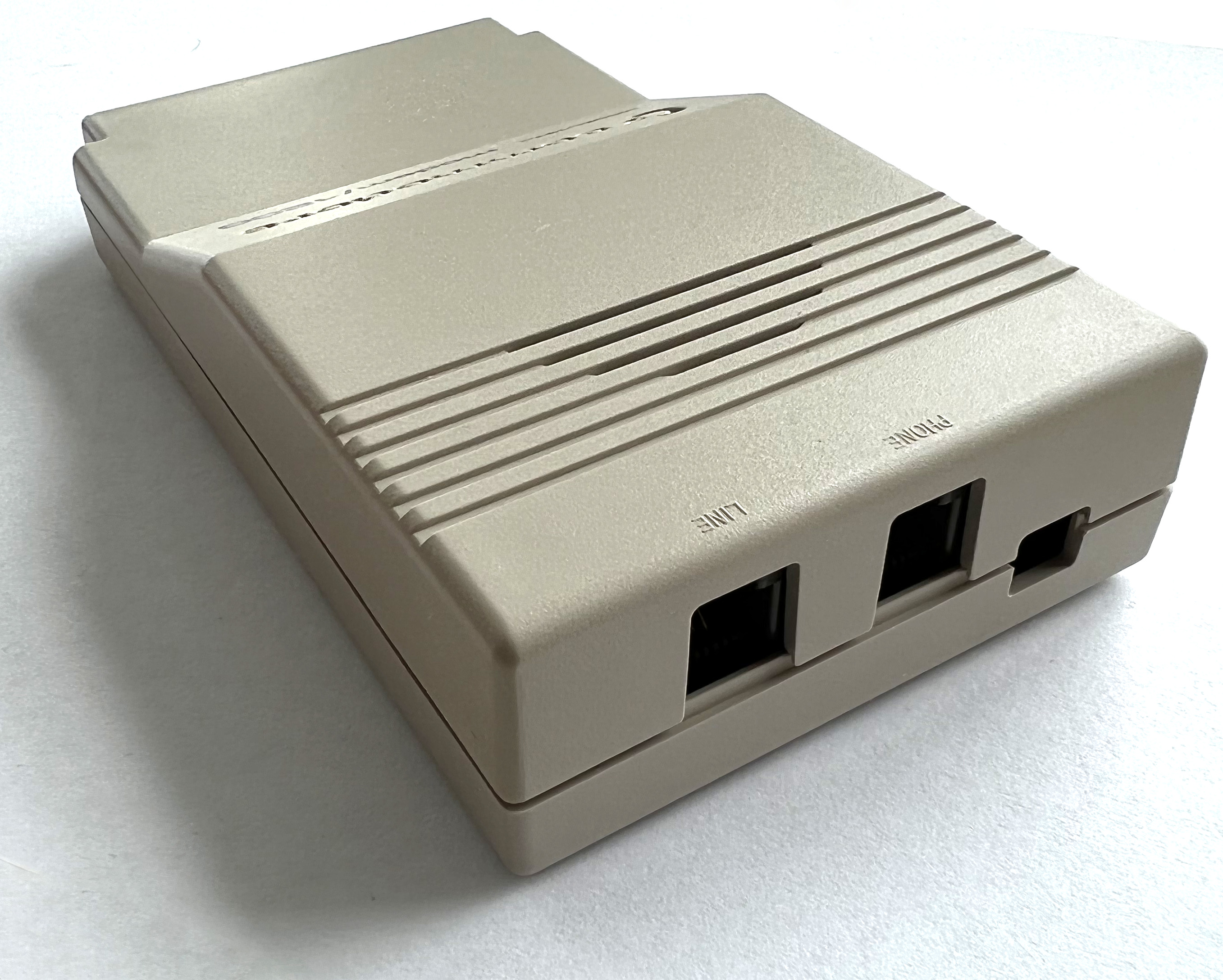
On the back, there are
- two phone line connectors. “LINE” is connected to the telephone network, and an existing telephone can be connected to the “PHONE” line.
- four DIP switches (default to down):
| DIP | Description | |
|---|---|---|
| 1 | Auto Answer Enable | down: auto-answer on second ring disabled |
| 2 | Carrier Detect Enable | down: carrier detect on pin H-K of edge connector (needed for Plus/4) |
| 3 | Speed Indicate Enable | down: speed indicate on pin J of edge connector |
| 4 | Data Terminal Ready | down: DTR always on (instead of computer controlled) |
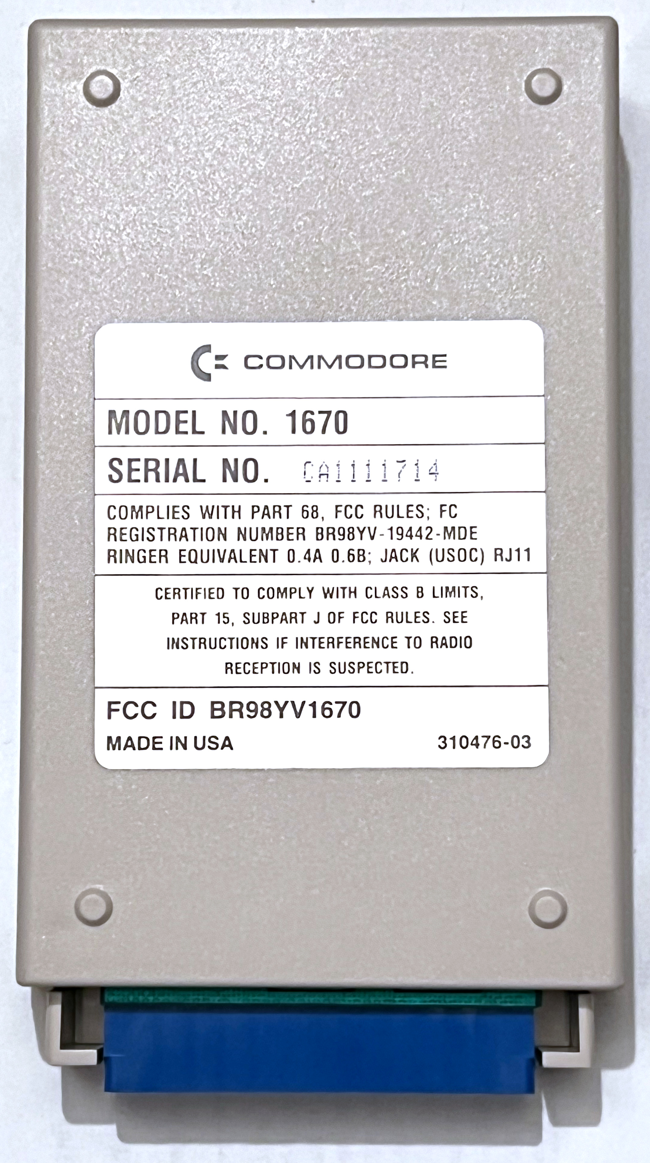
The label on the bottom says:
| C= COMMODORE |
| MODEL NO. 1670 |
| SERIAL NO. CA1111714 |
|
COMPLIES WITH PART 68, FCC RULES; FC REGISTRATION NUMBER BR98YV-19442-MDE RINGER EQUIVALENT 0.4A 0.6B; JACK (USOC) RJ11 |
|
CERTIFIED TO COMPLY WITH CLASS B LIMITS, PART 15, SUBPART J OF FCC RULES. SEE INSTRUCTIONS IF INTERFERENCE TO RADIO RECEPTION IS SUSPECTED. |
|
FCC ID BR98YV1670 MADE IN USA 310476-03 |
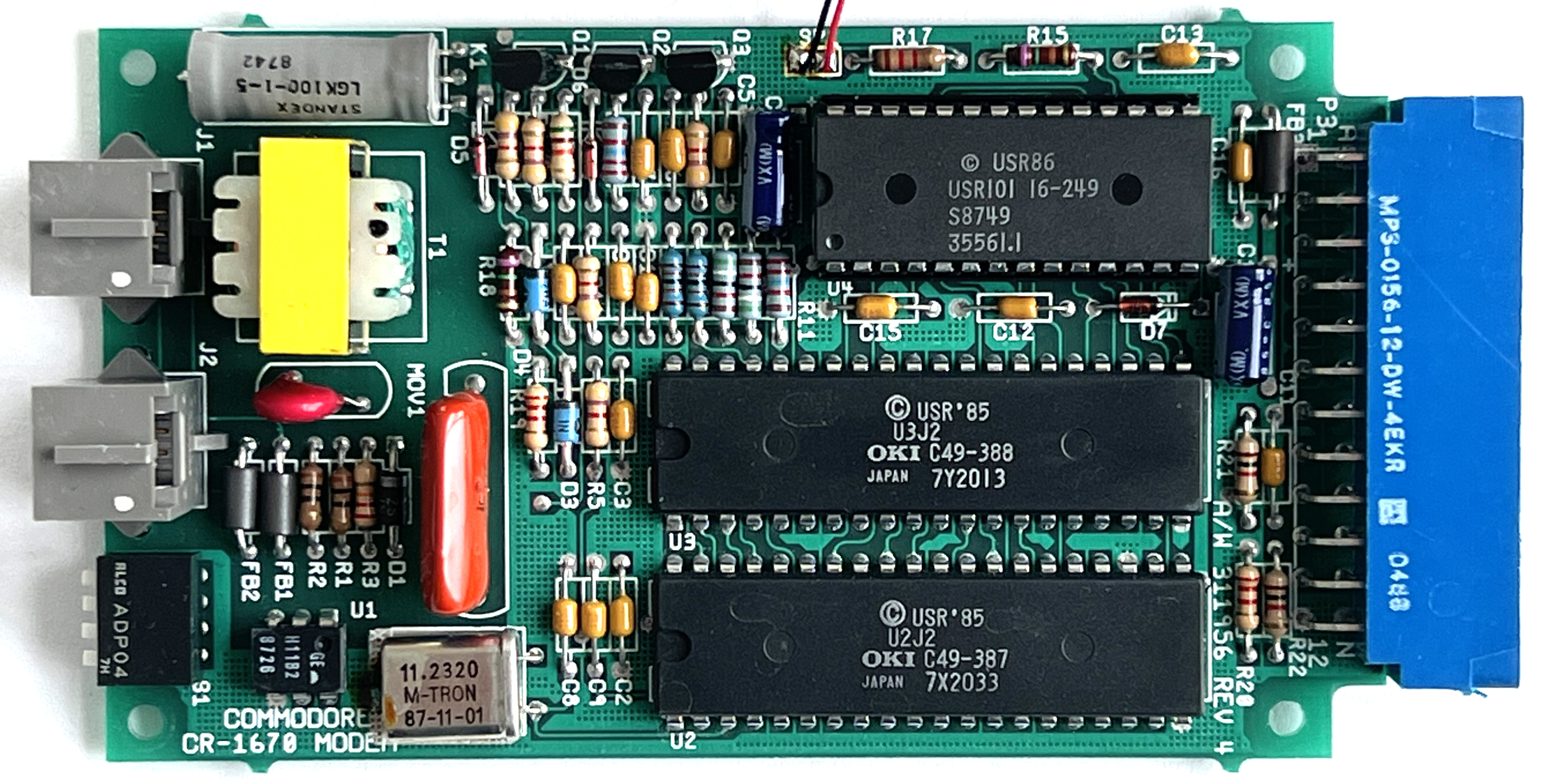
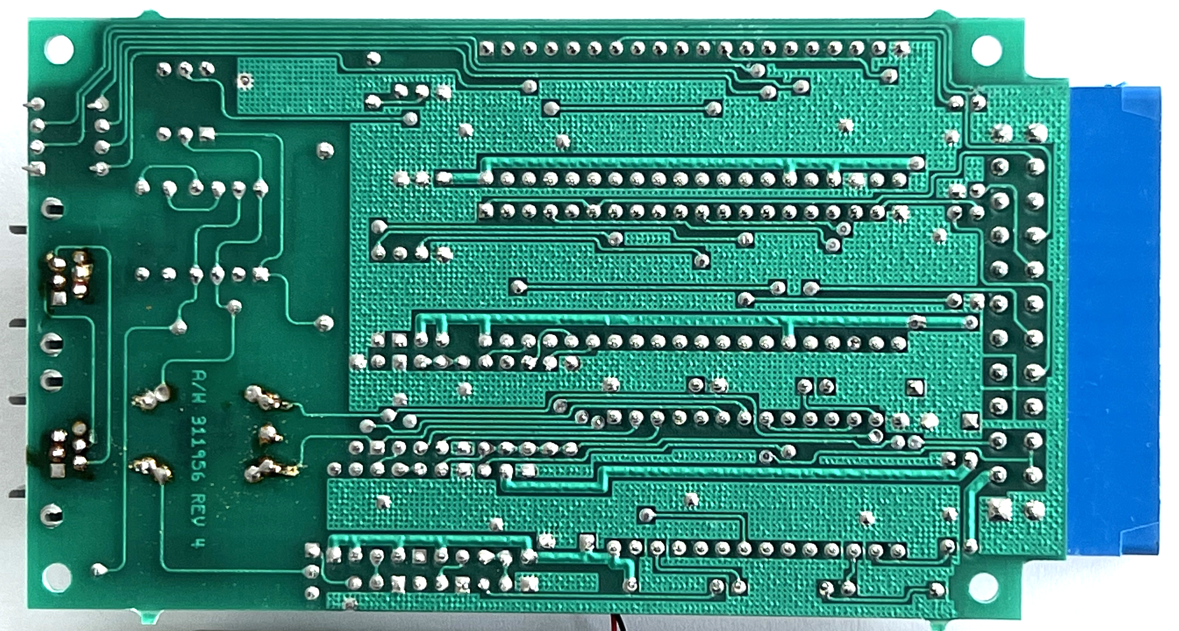
The board is marked “COMMODORE CR-1670 MODEM” and “A/W 311956 REV 4”.
The 1670 is based on a U.S. Robotics (“USR”) chipset:
- U2:
© USR'85 U2J2 / OKI C49-387 / JAPAN 7X2033: This is an OKI MSM80C49-387RS, a 80C49 microcontroller with 2KB of mask ROM and 128 bytes of RAM. “387” indicates which ROM image it contains. - U3:
© USR'85 U3J2 / OKI C49-388 / JAPAN 7Y2013: This is an OKI MSM80C49-388RS, another 80C49 microcontroller, with a different ROM image (“388”). - U4:
© USR86 / USR101 16-249 / S8749 / 35561: This socketed IC is probably the ROM that holds the bulk of the modem’s firmware.
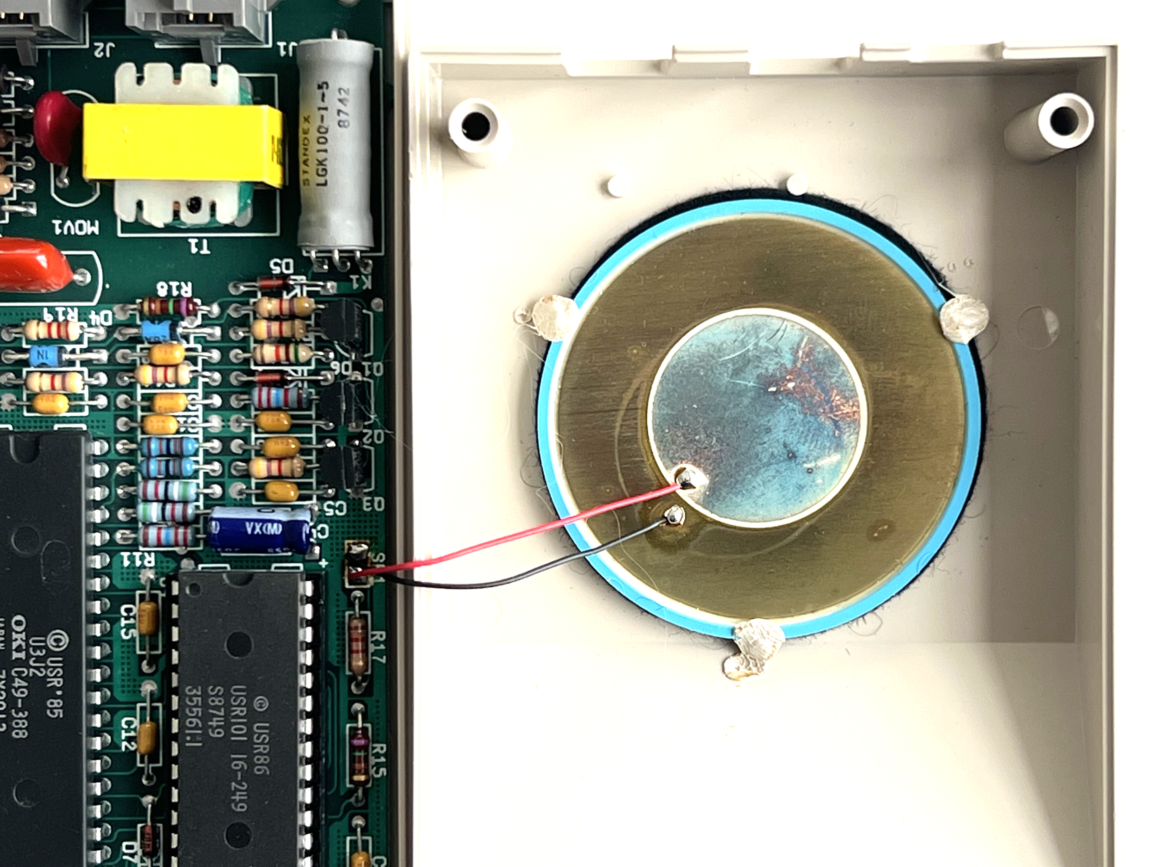
There is a speaker glued to the top shell that allows monitoring the audio data on the line.
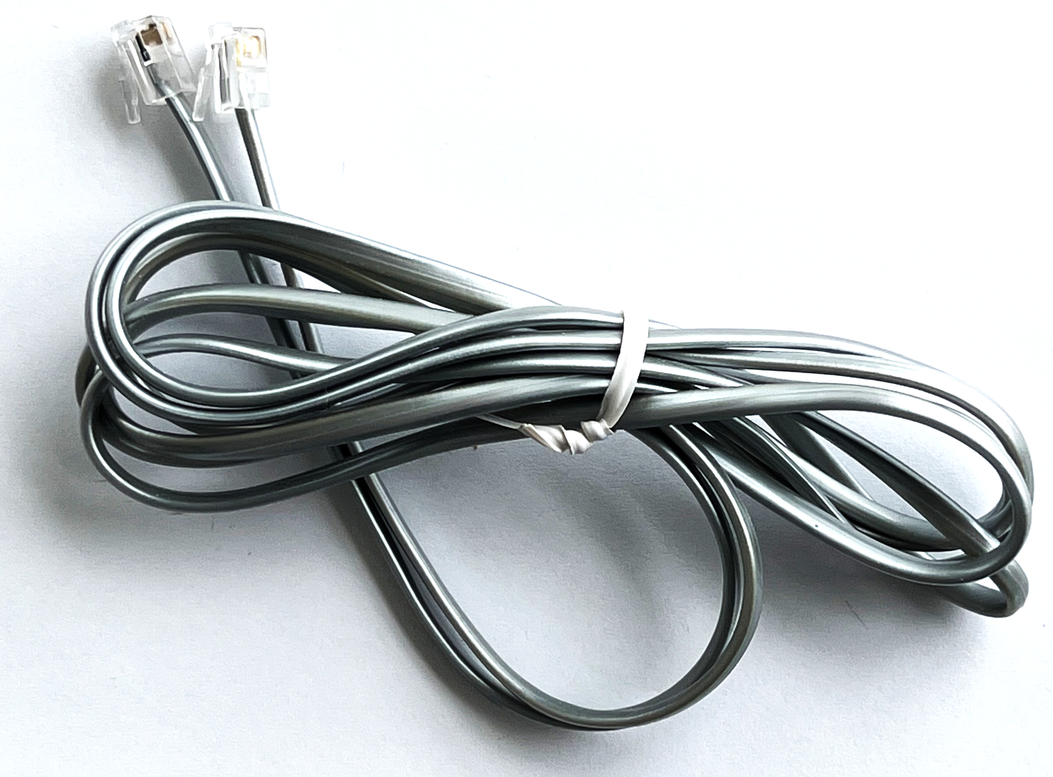
The modem comes with a phone cable.
Box

Manual
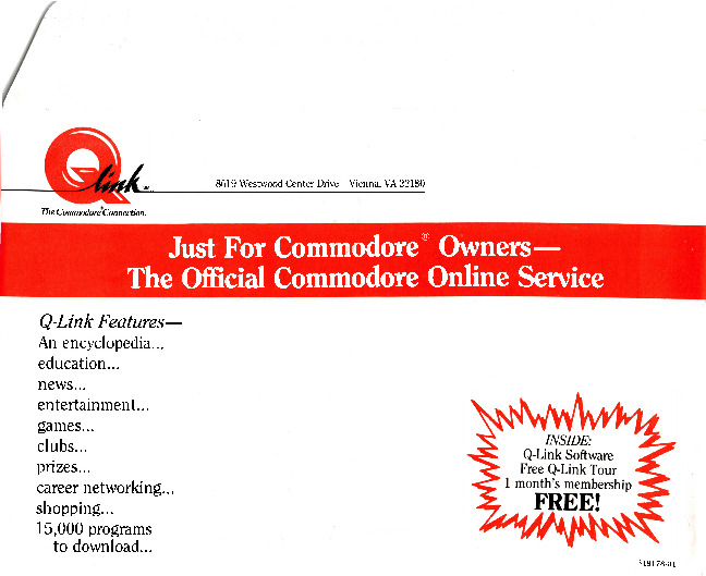
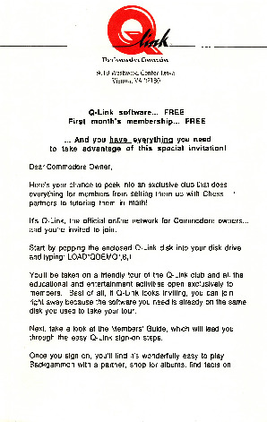
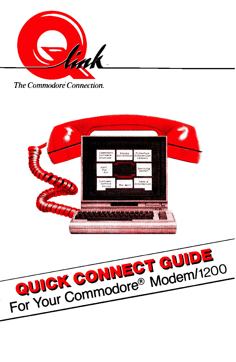
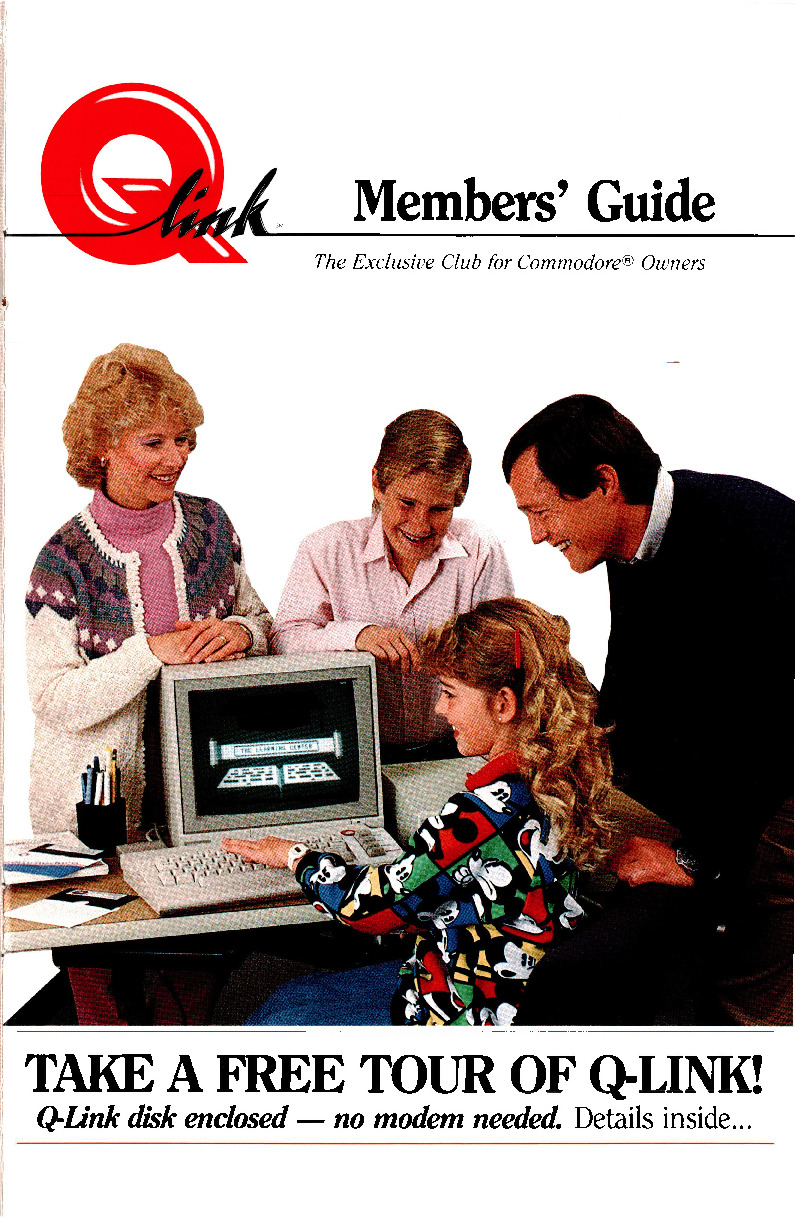
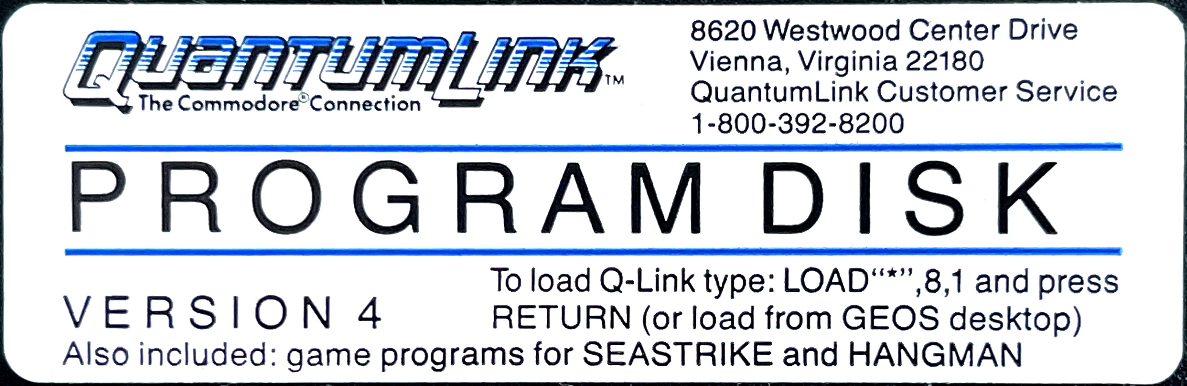
QuantumLink Material

More Box Contents
Disk
The Hayes/AT Interface
-
ATI/ATI0 (product code) prints
121 OK -
ATI1 (ROM checksum) prints
1003 OK -
The manual defines registers (
ATSn=a,ATSn?) 0-8, 10-12 and 16. Except for 16 (self test), they are identical to other U.S. Robotics modems – as late as the 1997 Sportster Flash x2! -
Register 9 is undocumented. Later U.S. Robotics manuals document it as:
Sets the required duration, in tenths of a second, of the remote modem’s carrier signal before recognition by your modem. (default: 6)
On the 1670, register 9 reads back as 6, so it may as well be the same feature.
-
The registers just seem to map to the 128 bytes of RAM of one of the 80C49 microcontrollers, they wrap around at 128, e.g. 130 is the same as 2. Here is a complete dump after power-on; much of the data may be random, but note the current
ATcommand (S19?) starting at register 0x11 (17):00000000 00 00 2b 0d 0a 08 02 1e |..+.....| 00000008 02 06 07 46 32 00 02 00 |...F2...| 00000010 00 53 31 39 3f ff ff 00 |.S19?...| 00000018 12 01 00 00 00 00 02 04 |........| 00000020 20 00 00 04 00 00 20 a4 | ..... .| 00000028 00 80 00 00 00 00 50 01 |......P.| 00000030 00 00 00 00 00 00 04 00 |........| 00000038 20 80 00 00 02 00 00 00 | .......| 00000040 98 02 00 00 00 40 02 80 |.....@..| 00000048 05 00 10 00 00 7f 47 81 |......G.| 00000050 00 00 0a 00 86 10 02 63 |.......c| 00000058 d4 23 30 24 bd 63 6e 63 |.#0$.cnc| 00000060 00 08 00 00 00 00 04 00 |........| 00000068 6b 00 00 00 e5 66 00 08 |k....f..| 00000070 80 60 00 65 01 3b 00 07 |.`.e.;..| 00000078 01 80 65 00 00 0a 01 00 |..e.....| -
Like all Bell 212A-compatible modems, when on a 1200 baud call, the data rate between the modem and the C64 is actually 1219 bits/sec. The manual states that it is necessary to specify this manual bitrate when using the KERNAL’s software RS232 implementation:
OPEN2,2,2,CHR$(0)+CHR$(0)+CHR$(61)+CHR$(1)
Modern versions of CCGMS won’t work with the 1670 for this reason.
Open Questions
- How to dump the ROM chip? I had no success reading it as a 2764..27512.
- How to dump the ROM of the 80C49 microcontrollers?
I might misremember, but I think that for the microcontroller to execute code from an external ROM of the regular 27xx type or similar you would need at least a chip that latches parts of the address bus due to multiplexing being used.
To read the external rom I would assume that you would either want to use custom software for some universal programmer, use custom software for any device with loads of GPIO pins, and emulate how the microcontroller accesses an external ROM.
P.S. IIRC The microcontroller can also have external ram. Not unthinkable that the external chip both contains rom and ram if more ram might had been needed. Not that likely, but still.
How to dump the 8049:
http://www.mattmillman.com/projects/hveprom-project/an-easy-to-build-mcs-48-8748-8749-8741-8742-8048-8049-programmer-reader/