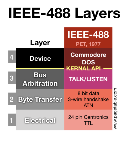
In the series about the variants of the Commodore Peripheral Bus family, this article covers the lowest two layers (electrical and byte transfer) of the IEEE-488 bus as found on the PET/CBM series.
NOTE: I am releasing one part every week, at which time links will be added to the bullet points below. The articles will also be announced on my Twitter account @pagetable and my Mastodon account @pagetable@mastodon.social.
- Part 0: Overview and Introduction
- Part 1: IEEE-488 [PET/CBM Series; 1977] ← this article
- Part 2: The TALK/LISTEN Layer
- Part 3: The Commodore DOS Layer
- Part 4: Standard Serial (IEC) [VIC-20, C64; 1981]
- Part 5: TCBM [C16, C116, Plus/4; 1984]
- Part 6: JiffyDOS [1985] (coming soon)
- Part 7: Fast Serial [C128; 1986] (coming soon)
- Part 8: CBDOS [C65; 1991] (coming soon)
History
Most computers from the early time of home/personal computers had printers connected through either Centronics or RS-232 and disk drives connected directly to the internal bus. For the 1977 PET, Commodore decided to go with a standard interface that would allow to connect several drives and printers to a single port: IEEE-488.
The interface standardized as IEEE-488 in the US and as IEC-625 internationally is also known as the Hewlett-Packard Interface Bus (“HP-IB”) and was originally designed in the late 1960s. It was popular mostly for test equipment, but also for printers.
IEEE-488 is a 8 bit parallel bus with the following properties:
- All participants are daisy-chained.
- One dedicated controller (the computer) does bus arbitration of up to 31 devices.
- One-to-many: Any participant can send data to any set of participants.
- A device has multiple channels for different functions.
- Data transmission is byte stream based.
This article covers layers 1 (electrical) and 2 (byte transfer) of IEEE-488 from the PET’s perspective. Differences to the standard are mentioned at the end.
Layer 1: Electrical
Connectors and Pinout
On the computer side, the PET uses a proprietary 24 pin edge connector:

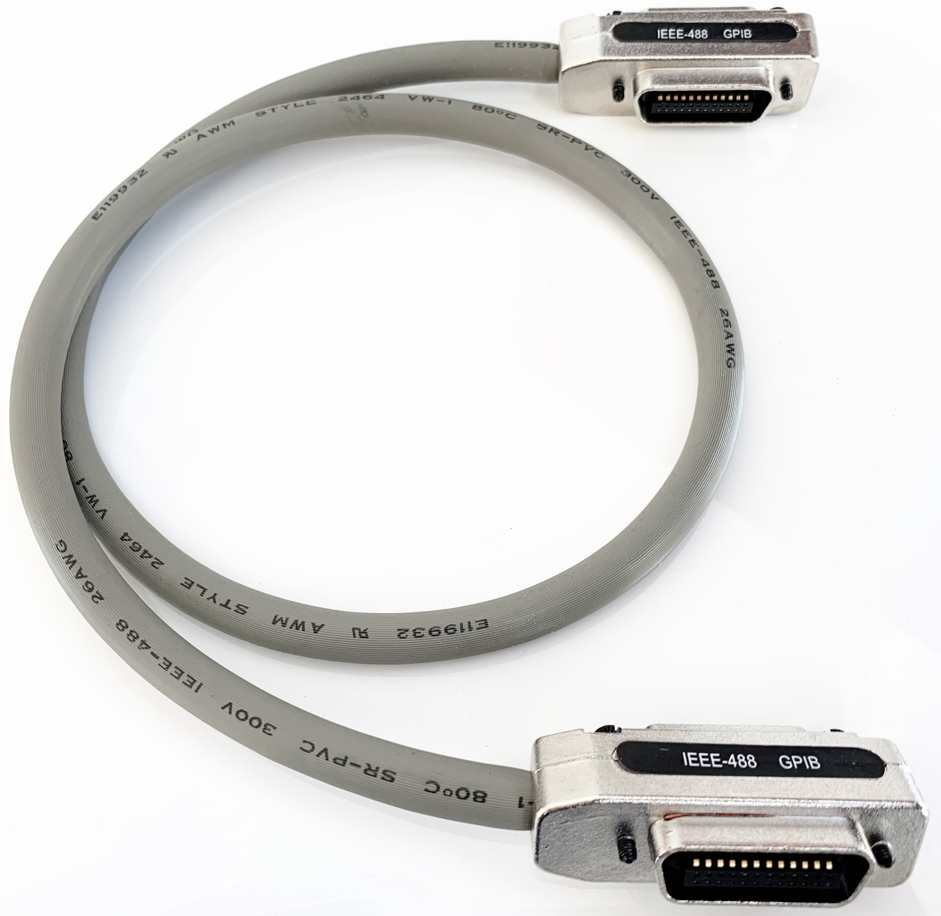
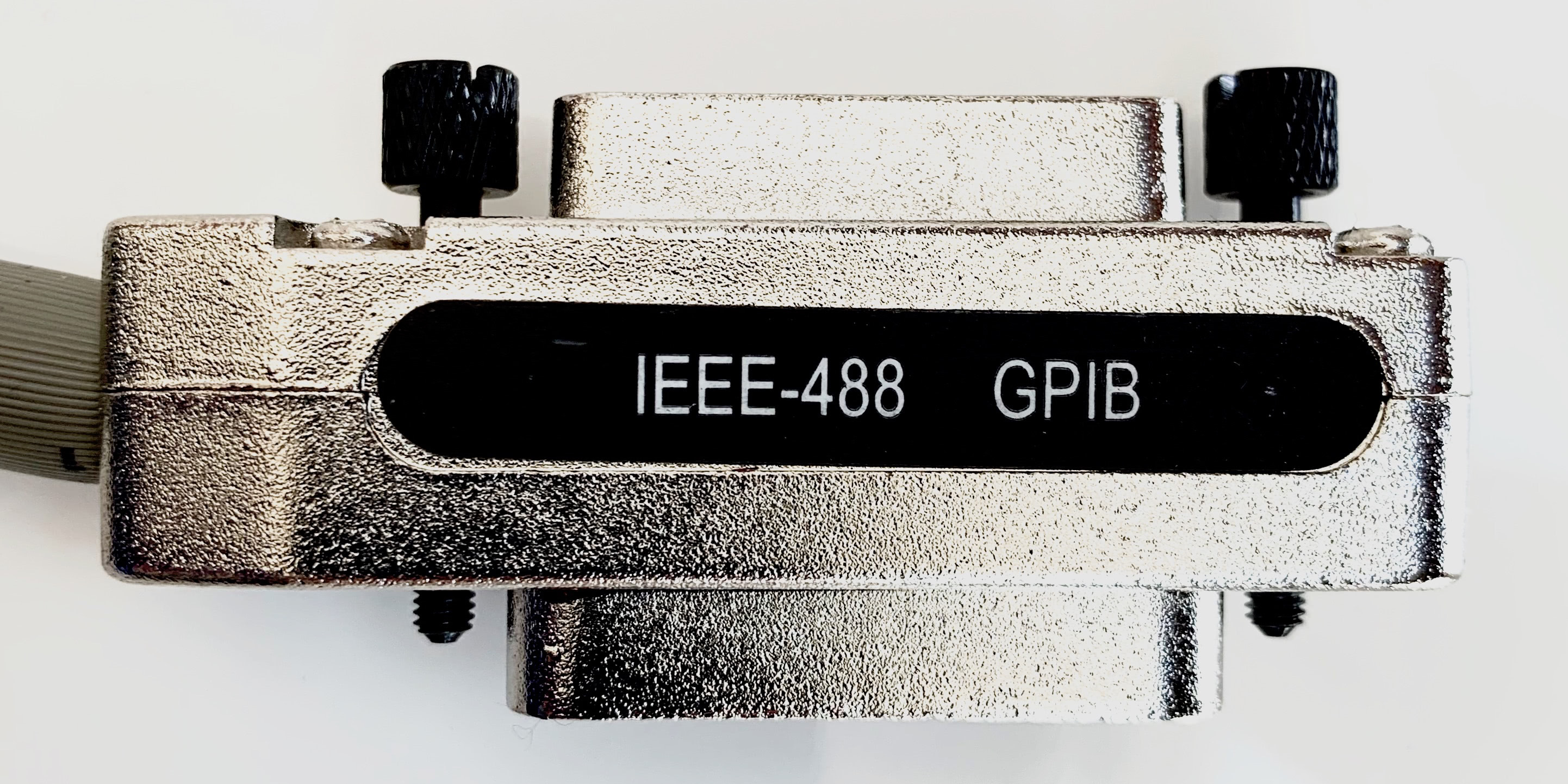
All devices use the standardized IEEE-488 connector, which is a 24 pin micro ribbon connector:

Devices usually only have a single micro ribbon connector, but the connectors of common IEEE-488 cables have one male and one female side, so the back side of every cable connector becomes the connector to the next device.
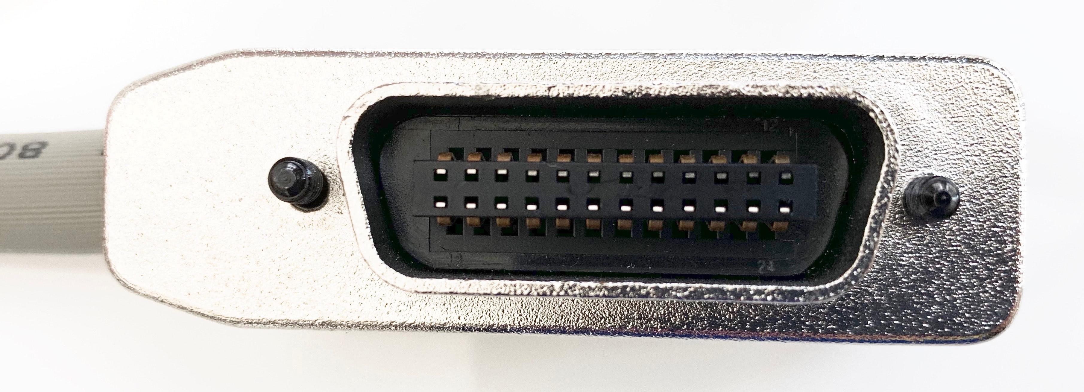
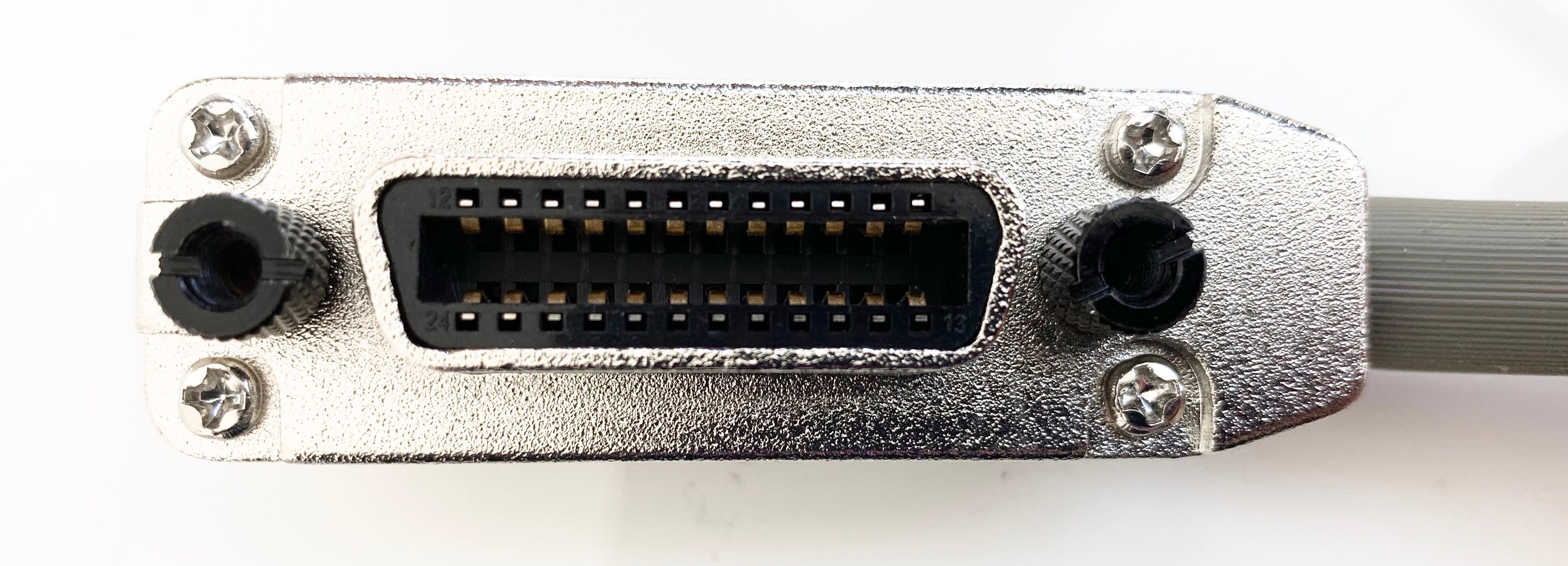
The pinout is similar across the two connectors:
| Pin | Signal | Description | Pin | Signal | Description |
|---|---|---|---|---|---|
| 1 | DIO1 | Data I/O | 13/A | DIO5 | Data I/O |
| 2 | DIO2 | Data I/O | 14/B | DIO6 | Data I/O |
| 3 | DIO3 | Data I/O | 15/C | DIO7 | Data I/O |
| 4 | DIO4 | Data I/O | 16/D | DIO8 | Data I/O |
| 5 | EOI | End Or Identify | 17/E | REN | Remote Enable |
| 6 | DAV | Data Valid | 18/F | GND | |
| 7 | NRFD | Not Ready For Data | 19/H | GND | |
| 8 | NDAC | No Data Accepted | 20/J | GND | |
| 9 | IFC | Interface Clear | 21/K | GND | |
| 10 | SRQ | Service Request | 22/L | GND | |
| 11 | ATN | Attention | 23/M | GND | |
| 12 | SHIELD | 24/N | GND |
- The eight DIO lines carry the data bytes.
- The NRFD, DAV and NDAC lines are used to perform handshaking.
- EOI, ATN, SRQ and REN are control lines.
- IFC is the RESET line for all devices.
Open Collector Logic
All signal lines are TTL open collector, which means:
- All participants of the bus can not only read, but also write to the line.
- When all participants write 0, the line will read back 0, but if any device writes 1, the bus will read back as 1.
- The logic is inverted: 5V is 0 (false), and 0V is 1 (true).
In other words: If the line is released by all bus participants, it will be 5V (logically 0), and any participant can pull it to 0V (logically 1).
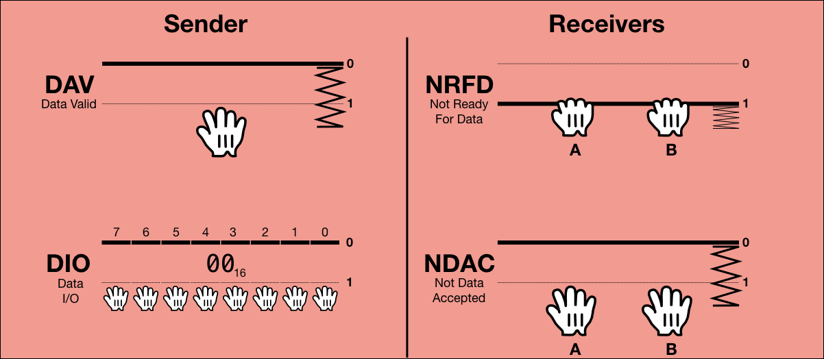
This can be visualized with two (or more) hands that can pull the line to 1, and a spring that pushes it to 0:
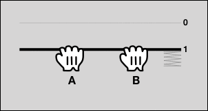
So when a line reads as 0, it is known that it is currently released by all participants, and if a line reads as 1, one or more participants are pulling it, but it is impossible to know who or even how many.
Layer 2: Byte Transfer
The basic byte transfer protocol of IEEE-488 is based on transmissions of byte streams from one sender to one or more receivers. Additional bus participants will remain silent. There are no fixed assignments of senders and receivers, the roles of sender and receiver are per transmission.
Sending Bytes
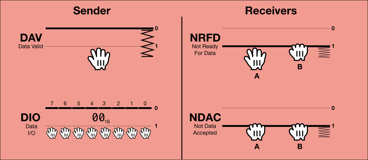
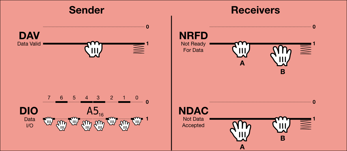
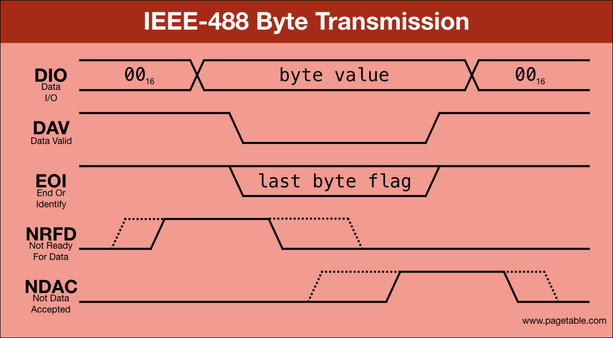
When transmitting data, the sender operates the DIO (Data I/O) and DAV (Data Valid) lines, while the receivers operate the NRFD (Not Ready For Data) and NDAC (Not Data Accepted) lines. All bus participants that don’t operate a line leave it released.
The basic idea is that the receivers signal that they are ready for data (NRFD = 0), the sender puts the data on the bus (DIO) and signals that the data is valid (DAV), and the receivers signal that they have accepted the data (NDAC = 0). This is called the 3-wire-handshake.
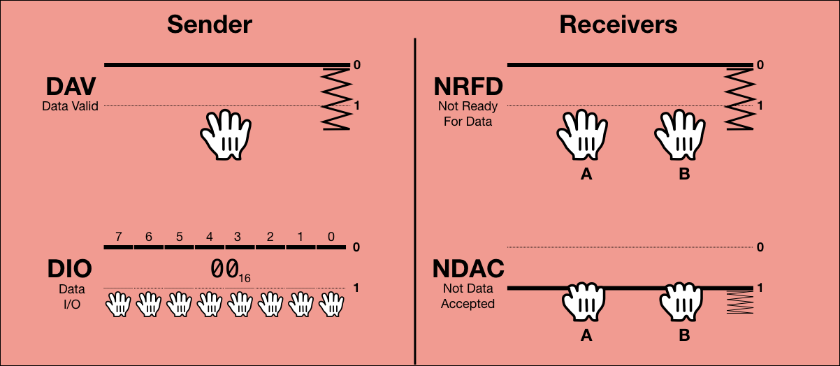
The following animation shows a byte being sent to two receivers.
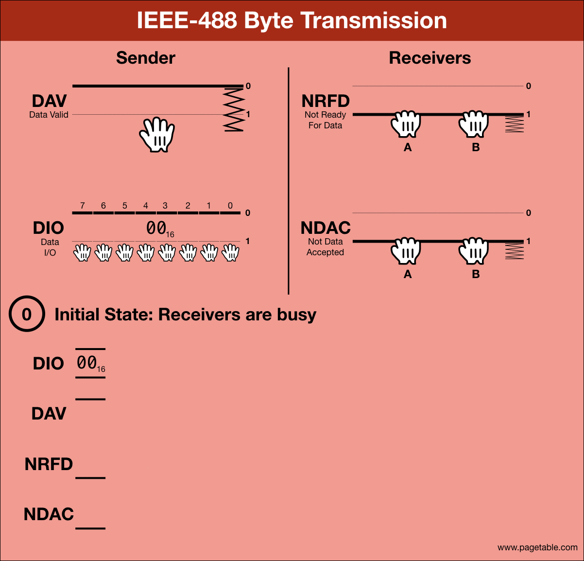
Let’s go through it step by step:
0: Initial State: Receivers are busy

In the initial state, the sender has the 8 data bits set to 0 and DAV to 0, meaning that there is no data available. All receivers have NDAC pulled, meaning that no data was accepted (yet). They may also have NRFD (not ready for data) pulled while they are busy doing other things.
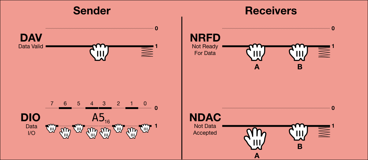
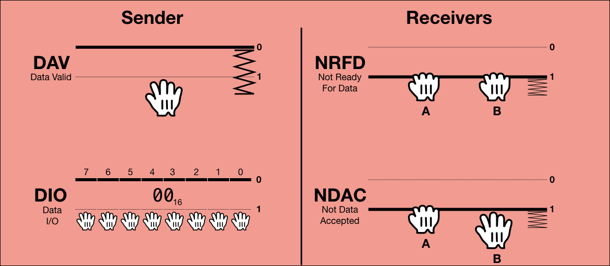
1: A is now ready to receive data
Transmission of a byte cannot begin until all receivers are ready to receive. So at some point the first receiver is done handling the previous byte it may have received and signals that it is ready for data by releasing NRFD. The NRFD wire is still pulled by the other receiver though, so its value is still 1.
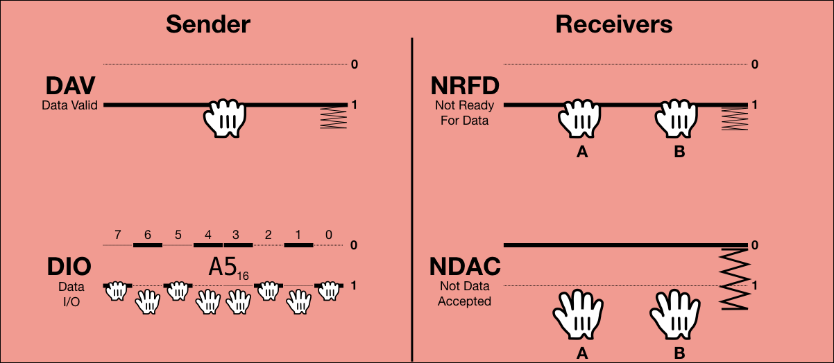
2: All receivers are now ready to receive data
Whenever the other receiver is ready to receive the next byte, it will also release NRFD, so it will now read back as 0: All receivers are ready to receive data.
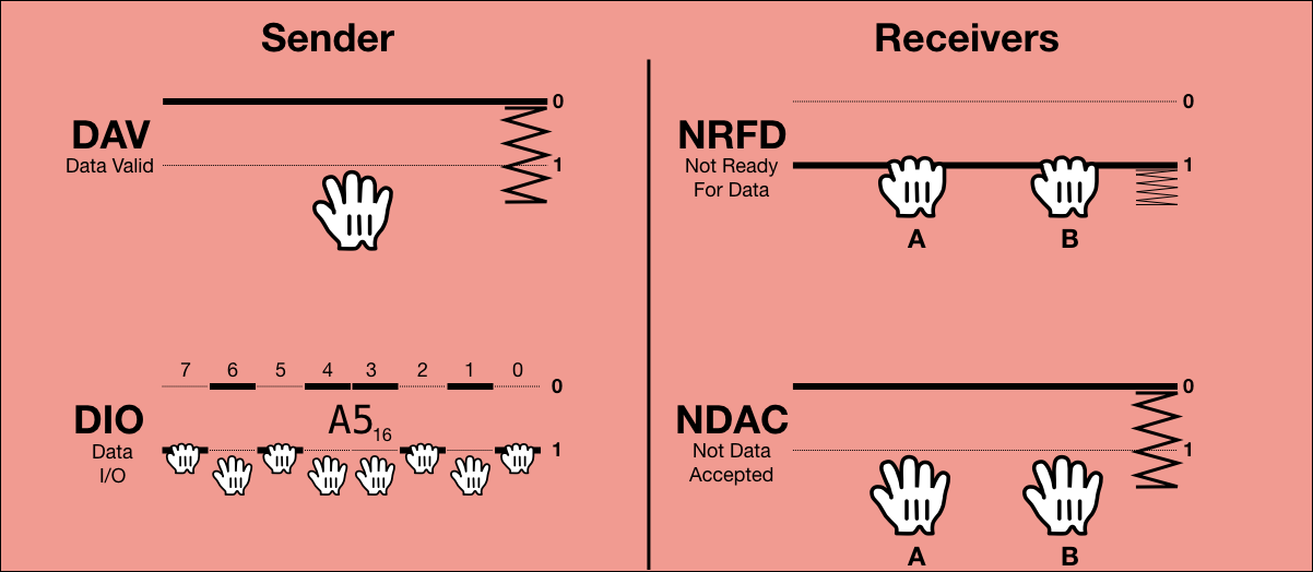
3: Sender puts data on the bus
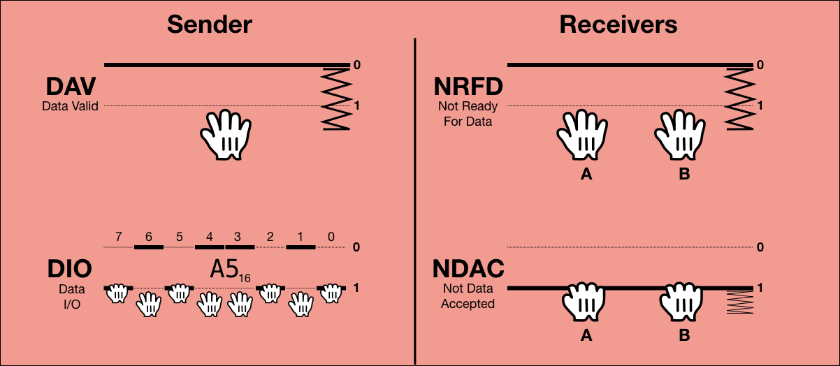
Triggered by NRFD being 0, the sender now puts the byte value onto DIO.
4: Data on bus is now valid
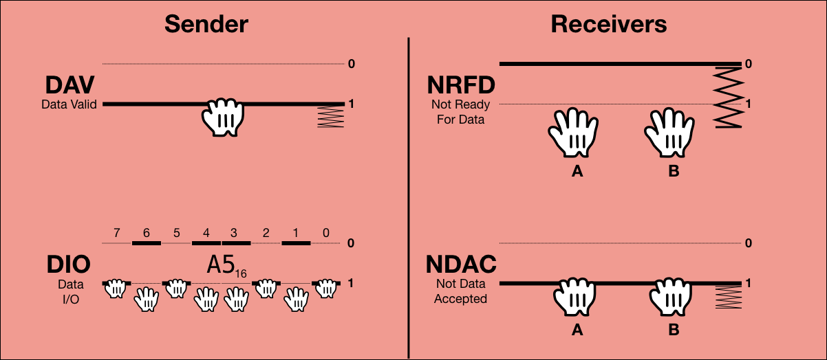
After that, the sender pulls DAV, signaling that the data in DIO is valid.
5: A is now busy again
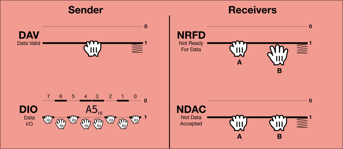
Triggered by DAV being 1, the receivers first have to signal that they are busy, so that after accepting the data, the sender won’t think the receivers are immediately ready for the next byte. So now, the first receiver pulls NRFD, so NRFD is 1.
6: A has accepted the data
Then, the first receiver reads the data from DIO and releases NDAC, signaling that it has accepted the data. But the other receiver is still pulling it, so NDAC is still 1.
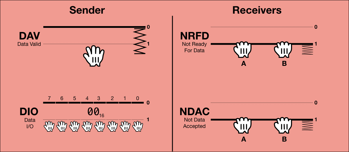
7: B is now busy
Before it can accept the data, the other receiver also has to signal that it is busy by pulling NRFD. The line was already 1 and will stay at 1.
8: All receivers have accepted the data
Then the other receiver reads the data from DIO and releases NDAC. NDAC is now 0, meaning all receivers have accepted the data.
9: Data on the bus is no longer valid
Triggered by NDAC being 0, the sender sents DAV back to 0, meaning the data in DIO is no longer valid.
10: Sender clears data on the bus
In order to revert to the initial state, the sender then clears the byte from the DIO lines and sets them back to 0.
11: A resets data accepted
Triggered by DAV being 0, the first receiver pulls NDAC.
12: B resets data accepted
Likewise, the other receiver pulls NDAC. All wires are now in the initial state again. All steps are repeated as long as there is more data to be sent.
Note that the protocol only specifies the triggers: For example, the receivers are to read the data from DIO once DAV = 1, so it would be just as legal for the the sender to put the data on DIO as early as step 1 (the PET does this, Commodore disk drives don’t), or combining the DAV and DIO writes (3/4 and 9/10) in one step.
Also, there is no ordering on which receiver pulls or releases its line first. The receivers don’t care about the other receivers, they only follow the protocol with the sender. The open collector property of the signal lines automatically combines the outputs of the different receivers.
End of Stream
If there is no more data to be transmitted, the sequence stops at step 12 (which is the same as step 0). It is the sender that decides whether it wants to transmit more data, but it is the receivers taking the first step for the next byte (NRFD = 0). Therefore, the sender already signals the end of the stream to the receivers while transmitting the last byte. It does this by pulling the EOI (“End Or Identify”) line to 1 while it is pulling DAV to 1.
As a side effect of this, IEEE-488 does not allow empty streams – they would have to be at least one byte long. Commodore’s version of the bus uses timeouts to signal this condition (see below).
Sending Commands
The assignment of senders and receivers to transmissions is the job of layer 3 (Bus Arbitration), described in part 3 of this series.
But there are also command transmissions, where one particiant can start a transmission to all other participants at any time.
Only so-called “controllers” may perform a command transmission, and on Commodore busses, there is always only one controller: the computer. All bus participants that are not controllers are called “devices”.
When the controller wants to send a command, it pulls the ATN (“Attention”) line. All devices on the bus have to immediately (i.e. within less than a clock cycle – Commodore drives do this using a hardware circuit) respond by pulling NDAC (“ATN Response Timing”), and participate in the 3-wire-handshake to receive the command byte stream.
The controller sends the command data like any other transmission, and releases ATN afterwards. It does not pull EOI during the transmission of the last byte, since the release of ATN signals the end of the stream already.
The encoding of commands is part of the layer 3 bus arbitrarion protocol.
Errors
When the sender wants to start the transmission of a byte, the bus must be in one of these two states:
- NRFD = 1, NDAC = X: At least one receiver is still busy, so wait until everyone is ready for data.
- NRFD = 0, NDAC = 1: All receivers are ready for data.
If NRFD = 0 and NDAC = 0, this means that there are no receivers present:
- There are either no other participants connected at all, so nobody can pull NRFD or NDAC,
- or there are participants connected, but they don’t want to receive, so they aren’t pulling NRFD or NDAC.
Just from the signals, receivers cannot detect whether there is a sender though. When trying to receive the first byte, the receivers signal their readiness with NRFD = 0. Then, as long as DAV = 0, it means the sender doesn’t have new data yet, and as soon as DAV = 1, it means the sender has data. The single line owned by the sender cannot communicate that there is nobody willing to send. A timing sidechannel (i.e timeouts) can though.
Timeouts
On the PET side, the Commodore version of IEEE-488 implements timeouts. By default, there are two steps that can time out:
- receiver timeout: After the PET as the sender signals that the data is valid by pulling DAV, the receivers have to release NDAC, i.e. accept the data within 64 µs.
- sender timeout: After the PET as the receiver signals that it is ready for data by releasing NRFD, the sender has to pull DAV, i.e. provide data within 64 µs.
The receiver timing requirement can easily be met if the receiver is waiting for the next byte in a tight loop and doesn’t have interrupts enabled. All it has to do is take the byte, buffer it, and release NDAC. It then has time to process it.
The sender timeout is problematic for two reasons:
- Since it is the receiver that starts the transmission of a byte, and the sender that has to react within 64 µs, there might not be enough time for the sender to actually retrieve the next byte e.g. from disk. Therefore, the sender is required to retrieve the byte during the transmission of the previous byte, e.g. while during DAV = 1, which cannot time out.
- Also, the timer starts running as soon as the PET releases NRFD. In theory, there could be more receivers next to the PET that have to release NRFD as well before the sender is even allowed to send the data. So this timeout will easily break this case. (This is fixable and could be considered an implementation bug.)
Mostly for compatibility with non-Commodore IEEE-488 devices (and also fixing the latter problem), timeouts can be disabled globally using the KERNAL call “SETTMO” ($FFA2) with A = $80.
In addition to being able to recover from malfunctioning devices, timeouts are also an implicit communication channel: If a sender is asked to perform a transmission but doesn’t actually have any data, it will signal this by timing out. Therefore, turning off the timeout will break the “FILE NOT FOUND” case for Commodore drives on layer 4.
Timing
Apart from ATN Response Timing and the two steps that have timeouts, IEEE-488 on the PET is has no timing constraints. A sender can stall for an arbitrary amount of time (in the DAV = 1 phase, step 4), e.g. in the case of a disk drive fetching data from disk, and a receiver can stall for an arbitrary amount of time (in the NRFD = 1 phase, step 0), e.g. in the case of a printer that is out of paper.
Additionally, the open collector property of the handshake lines allows the slowest receiver on the bus to control the transmission speed.
Standards-Compliance
The PET version of IEEE-488 is very close to the original specification of the bus and can therefore support most standard equipment.
On the hardware side, all signals are accessible, with the exception of REN (“Remote Enable”), which is connected to ground (logically true), and would otherwise have allowed devices to work standalone.
On the software side, there is no support for the SRQ (“Service Request”) line, which is supposed to allow a device to signal that it wants to be serviced. This is basically an IRQ line. While the signal is accessible from the PET, there is no software support, and no Commodore devices make use of it.
And as mentioned above, the PET uses timeouts by default, which can be disabled.
Next Up
Part 2 of the series of articles on the Commodore Peripheral Bus family will cover Layer 3: Bus Arbitration.
This article series is an Open Source project. Corrections, clarifications and additions are highly appreciated. I will regularly update the articles from the repository at https://github.com/mist64/cbmbus_doc.
References
- Fisher, E. R., & Jensen, C. W.: PET and the IEEE 488 Bus (GPIB). Berkeley, Calif: OSBORNE/McGraw-Hill, 1982. ISBN 0-931988-31-4.
- Keller, R. & Hurling H.: IEC-Bus – im Labor bewährt. in: c’t Magazin für Computer und Technik, 9/87, p. 187-192. ISSN 0724-8679.
- PETdoc.txt
- cbmsrc – Original source code of various Commodore computers and peripherals