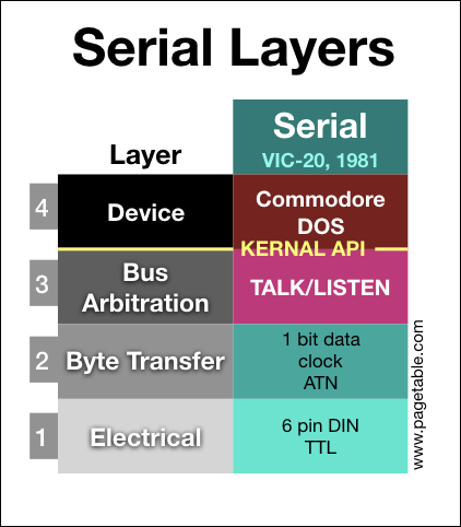
In the series about the variants of the Commodore Peripheral Bus family, this article covers the lowest two layers (electrical and byte transfer) of the “Standard Serial” bus as found on the VIC-20/C64 as the main bus, but also supported by all other Commodore home computers.
NOTE: I am releasing one part every week, at which time links will be added to the bullet points below. The articles will also be announced on my Twitter account @pagetable and my Mastodon account @pagetable@mastodon.social.
- Part 0: Overview and Introduction
- Part 1: IEEE-488 [PET/CBM Series; 1977]
- Part 2: The TALK/LISTEN Layer
- Part 3: The Commodore DOS Layer
- Part 4: Standard Serial (IEC) [VIC-20, C64; 1981] ← this article
- Part 5: TCBM [C16, C116, Plus/4; 1984] (coming soon)
- Part 6: JiffyDOS [1985] (coming soon)
- Part 7: Fast Serial [C128; 1986] (coming soon)
- Part 8: CBDOS [C65; 1991] (coming soon)
Naming and Context
First let’s clarify the naming. Commodore calls the three-wire protocol used e.g. by the Commodore C64 and the 1541 disk drives “Serial” in its reference documents. Later documentation calls it “Standard Serial” to distinguish it from the later backwards-compatible “Fast Serial”1 protocol of the C128. This also matches the naming in Commodore’s source code, where the protocol is called “serial”2.
“Standard Serial” is based on the PET’s parallel IEEE-488 bus (covered in part 1), which was standardized internationally as IEC-625. In Europe, IEEE-488 was therefore commonly referred to as the “IEC bus”. The serial version was then often called “Serial IEC”, even though this variant was not an IEC standard. Finally, the “serial” attribute was often dropped in European books and magazines, which is why “Standard Serial” is most often refered to as just the “IEC bus”.
There are two extensions to Standard Serial: The already mentioned “Fast Serial” (C128), as well as the third party “JiffyDOS”. They both share the same basic idea but are incompatible with each other. Both protocols also use the same cable as Standard Serial and are completely backwards-compatible with it. If they detect that their peers also speak the improved protocol, they will then switch to it. Fast Serial and JiffyDOS will be covered in separate articles.
History and Development
Commodore had been using the standard IEEE-488 bus on the PET series of computers and its disk drives and printers. Unhappy with the price of the parallel connectors and cables, they developed a serial version of layers 1 and 2 of the protocol for the upcoming VIC-20 (1981).
The design goal was to retain all of the core properties of the IEEE-488 bus:
- All participants are daisy-chained.
- One dedicated controller (the computer) does bus arbitration of up to 31 devices.
- One-to-many: Any participant can send data to any set of participants.
- A device has multiple channels for different functions.
- Data transmission is byte stream based.
The challenge was to reduce the 16 data lines of IEEE-488 down to 5 within these constraints:
| IEEE-488 Signal | Description | Serial Signal |
|---|---|---|
| DIO1-8 | Data I/O | DATA, CLK |
| EOI | End Or Identify | (timing) |
| DAV | Data Valid | (CLK) |
| NRFD | Not Ready For Data | (DATA) |
| NDAC | No Data Accepted | (timing) |
| IFC | Interface Clear | RESET |
| SRQ | Service Request | SRQ |
| ATN | Attention | ATN |
| REN | Remote Enable | – |
- Data: Instead of transmitting 8 bits in parallel, they are sent serially, using a CLK and a DATA line.
- Handshake: The function of the DAV and NRFD lines is taken over by the CLK and DATA lines. There is no NDAC signal, accepting data is based on timing.
- Management: REN (already unsupported on the PET) is removed. EOI is removed, the information is now transmitted through a timing sidechannel. RESET (IFC), SRQ and ATN are retained.
One property they could not keep was the relaxed timing requirement of IEEE-488: At most points in an IEEE-488 communication, any participant can stall for any amount of time. This makes it easy to implement the protocol completely in software, without any hardware that would guarantee strict timings. Serial on the other hand was designed with a dedicated hardware shift register in mind.
Layer 1: Electrical
Connectors and Pinout
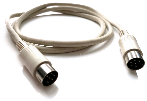
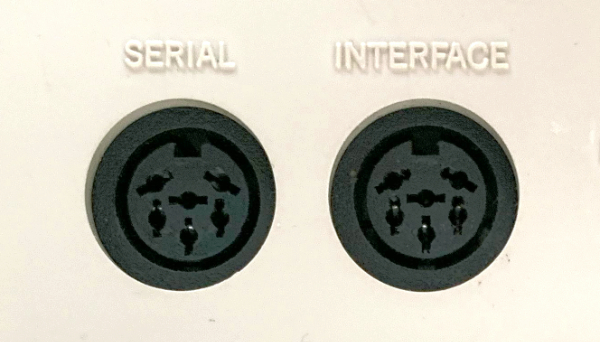
Both computers and devices use female 6-pin DIN 45322 connectors.

Since devices can be daisy-chained, most peripherals have two serial ports to connect to both the previous device (or the computer) and to the next device, if any. Either port can be used for the previous or the next device in the chain, but some devices labeled them one way anyway.
This is the pinout:
| Pin | Signal | Description |
|---|---|---|
| 1 | SRQ | Service Request |
| 2 | GND | Ground |
| 3 | ATN | Attention |
| 4 | CLK | Clock |
| 5 | DATA | Data |
| 6 | RESET | Reset |
- The CLK and DATA line carry the data and are used for handshaking.
- ATN and SRQ are control lines. (SRQ is unused, see below.)
- The RESET line resets all devices.
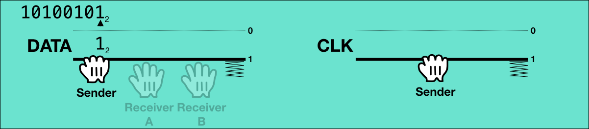
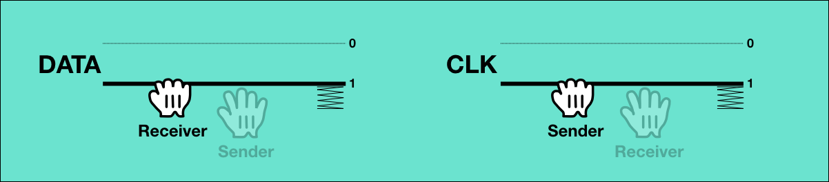
Open Collector Logic
All signal lines are TTL open collector, which means:
- All participants of the bus can not only read, but also write to the line.
- When all participants write 0, the line will read back 0, but if any device writes 1, the bus will read back as 1.
- The logic is inverted: 5V is 0 (false), and 0V is 1 (true).
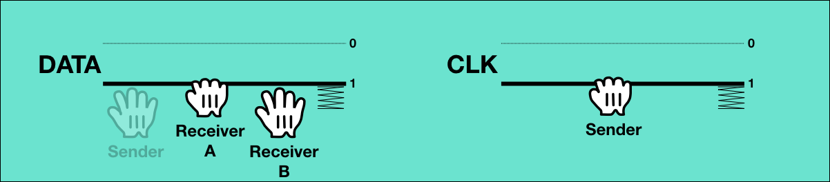
In other words: If the line is released by all bus participants, it will be 5V (logically 0), and any participant can pull it to 0V (logically 1).
This can be visualized with two (or more) hands that can pull the line to 1, and a spring that pushes it to 0:
So when a line reads as 0, it is known that it is currently released by all participants, and if a line reads as 1, one or more participants are pulling it, but it is impossible to know who or even how many.
Layer 2: Byte Transfer
Like with IEEE-488, the basic byte transfer protocol of the Serial Bus is based on transmissions of byte streams from one sender to one or more receivers. Additional bus participants will remain silent. There are no fixed assignments of senders and receivers, the roles of sender and receiver are per transmission.
Sending Bytes
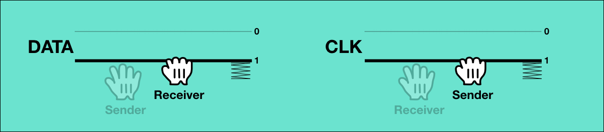
For the transmission of a byte stream, just two wires, CLK and DATA are used. The CLK line is exclusively operated by the sender, while the DATA line is operated by the sender during the transmission of bits, and by the receivers between the transmission of bytes.
The CLK line is the sender’s handshake, and outside of bit transmission, the DATA line is the receiver’s handshake.
The following animation shows a byte being sent to two receivers.
Let’s go through it step by step:
0: Initial State
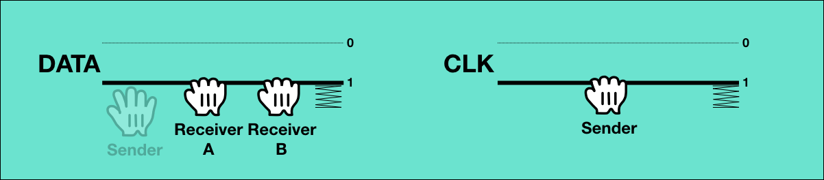
In the initial state, the sender is holding the CLK line to indicate that it it is not ready to send. The receivers are holding the DATA line, meaning they are not ready to receive.
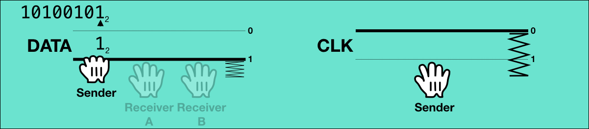
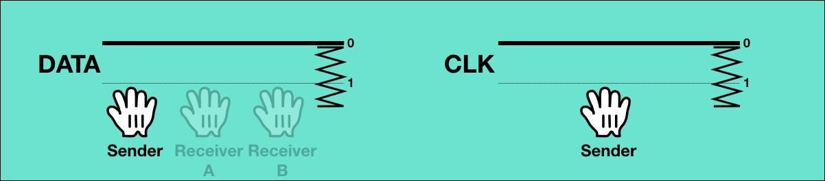
1: Sender is ready to send
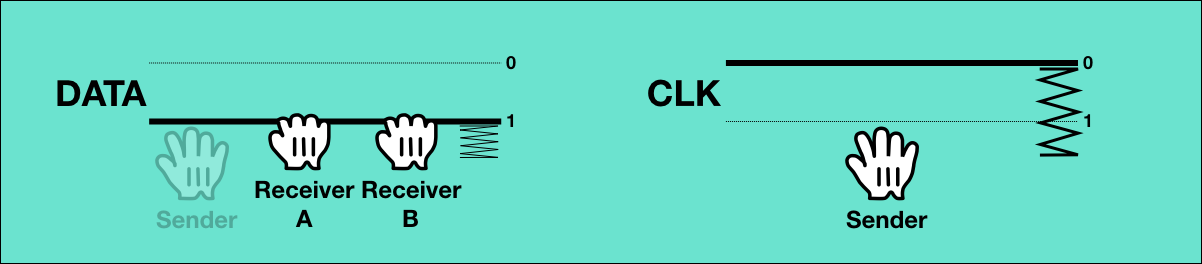
Transmission of a new byte is initiated by the sender, indicating that it is ready to send by releasing the CLK line.
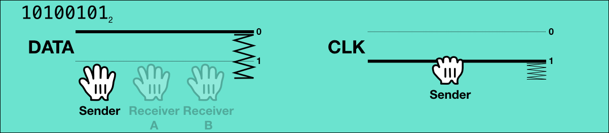
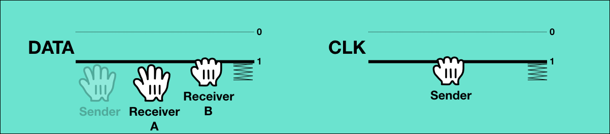
2: A is now ready to receive data
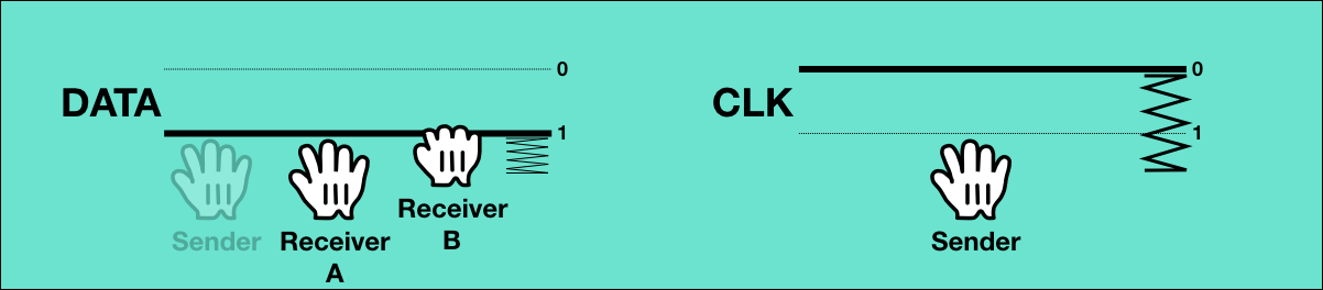
Transmission of the bits cannot begin until all receivers are ready to receive. So at some point the first receiver is done handling the previous byte it may have received and signals that it is ready for data by releasing DATA. The DATA wire is still pulled by the other receiver though, so its value is still 1.
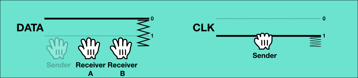
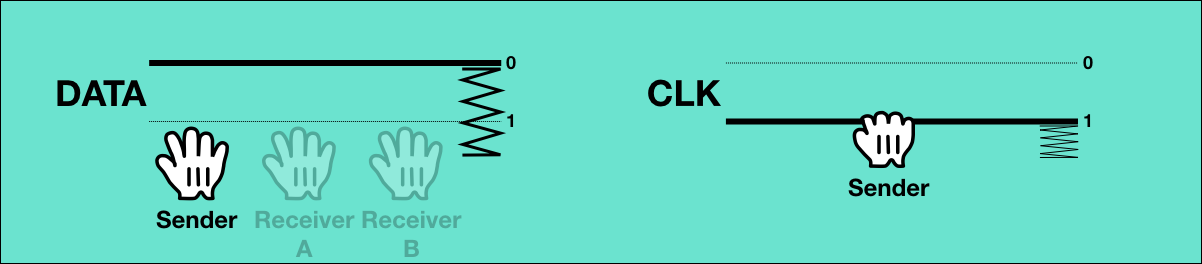
3: All receivers are now ready to receive data

Whenever the other receiver is ready to receive the next byte, it will also release DATA, so it will now read back as 0: All receivers are ready to receive data.
During the actual transmission of the data, both CLK and DATA are now operated by the sender.
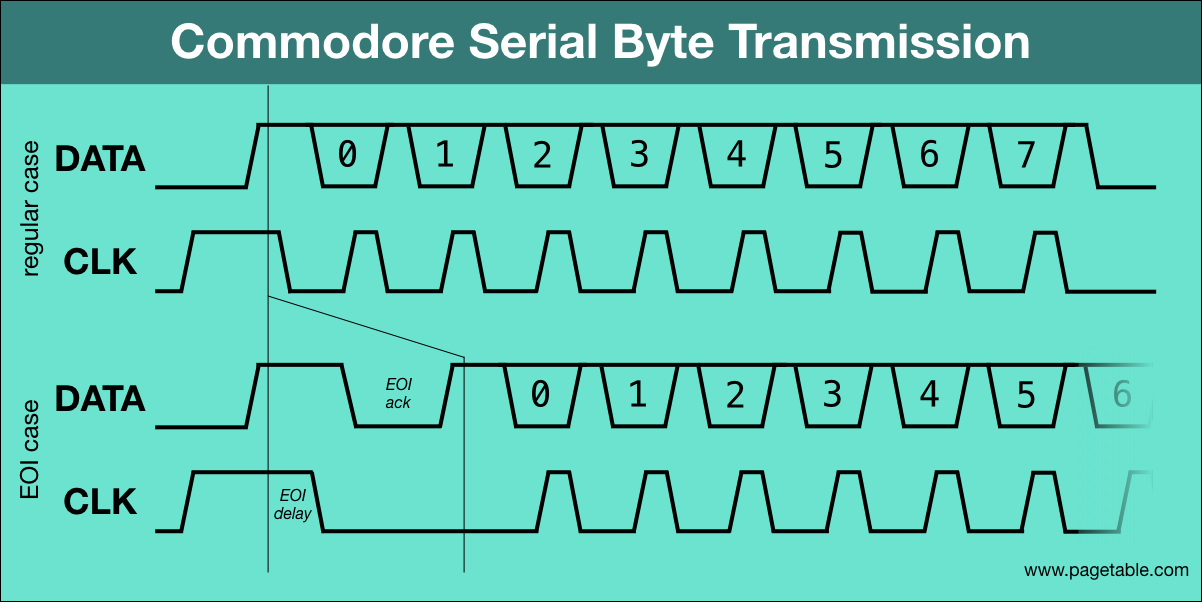
4: Data is not valid – hold for 60 µs

For the transmission of the bits, the CLK line will indicate whether the data on the DATA line is valid. So for the initial state, the sender pulls CLK, indicating that data is not valid.
Since both lines are now controlled by the sender, there is no back channel for the receivers, and they cannot acklowledge any state transition. So from now on, everything is based on timing. As a part of this, the CLK line has to be pulled for at least 60 µs until it is released again in step 6, to make sure the receiver notices the state change.
5: Sender puts data bit #0 onto the wire
The sender now puts the value of the first bit into DATA.
6: Data is now valid – hold for 60 µs
After that, the sender releases CLK, signaling that the data bit in DATA is valid.
There is no way for the receivers to signal “data accepted” for the bit. The sender must hold this state for at least 60 µs, and receivers must be able to accept the bit within this time.
7: Data is not valid – hold for 60 µs
After the 60 µs, the sender pulls CLK again to signal that the data is not valid, and releases the DATA line.
8-27: Repeat steps 5-7 for bits #1 to #7
The wires are in the same state again as in step 4, before sending the bit. The seven remaining bits will be transmitted the same way: CLK=1 for 60 µs, then CLK=0 for 60 µs with a data bit on DATA, and so on.
28: Data is not valid
Like for the previous bits, the last step of the last bit has the sender pulling CLK and releasing DATA.
From now on, the DATA line will be operated by the receivers again.
29: Receiver A is now busy again
Once all 8 bits have been transmitted, the receivers have to signal within 1000 µs that they are busy, so that after accepting the data, the sender won’t think the receivers are immediately ready for the next byte3. So now, the first receiver pulls DATA, so DATA is 1.
30: Receiver B is now busy

The other receiver also has to signal that it is busy by pulling DATA. The line was already 1 and will stay at 1. All wires are now in the initial state again. After a minimum delay of 100 µs (“between bytes time”), the sender can start repeating the sequence as long as there is more data to be sent.
Note that the protocol only specifies the triggers: For example, the receivers are to read the bit from DATA while CLK = 0, so it would be just as legal in step 7 for the the sender to hold CLK and release DATA in two steps (the 1541 does this, the C64 doesn’t).
Also, there is no ordering on which receiver pulls or releases its line first. The receivers don’t care about the other receivers, they only follow the protocol with the sender. The open collector property of the signal lines automatically combines the outputs of the different receivers.
End of Stream
If there is no more data to be transmitted, the sequence stops at step 30 (which is the same state as step 0). In this step, there is no way for the sender to signal the end of the stream, because it only controls one bit (0 = ready to send the next byte, 1 = it has more data but is not ready to send yet). Therefore, the sender already signals this during the transmission of the last byte. The number of wires for carrying information is still limited, but it can do it through a timing sidechannel4. (Consistent with IEEE-488, this event is called “EOI”, “End Or Identify”.)
3: Sender delays for 256 µs to signal EOI
To indicate the end of the stream, the sender delays step 4 by at least 200 µs. That is, after the sender has signaled that it has more data available (CLK = 0), and after all receivers have signaled that they are ready for data (DATA = 0), the sender doesn’t immediately pull the CLK line to start transmission.
4: Data is not valid

After the delay, it then pulls CLK, signaling that the data is not valid.
4a: Receiver A acknowledges EOI – hold for 60 µs

All receivers have to acknowledge that they have understood the EOI signal. So the first receiver will
do this by holding the DATA line for at least 60 µs.
4b: Receiver B acknowledges EOI – hold for 60 µs

The other receiver also has to hold the DATA line for 60 µs.
4c: A has finished acknowledging EOI
After the delay, the first receiver releases DATA agin. The wire is still pulled by the other receiver though, so its value is still 1.
4d: B has finished acknowledging EOI
After its delay, the other receiver will also release DATA, so it will now read back as 0.
After the sender has signaled EOI, it will wait for the DATA line to become 1, and then 0 again, until resuming the transmission of the final byte at step 5.
Empty Stream
With EOI being signaled during the transmission of the last byte of a stream, this method does not allow empty streams.
There is a separate mechanism for this case, also using timing: At step 3 of what would be the transmission of the first byte, the sender just completely stops, and leaves both DATA and CLK released.
Based on the time the transition from step 3 to step 4 takes, one of three different events is signaled:
- 0-256 µs: The following byte is not the last one in the stream.
- 256-512 µs: The following byte is the last one in the stream.
- 512+ µs: The stream is empty, the receiver will not transmit anything.
The empty stream case is equivalent to the IEEE-488 sender timeout, which is also what it is called in the Standard Serial specification. Commodore DOS (layer 4) interprets an empty stream as a “FILE NOT FOUND” condition.
Sending Commands
The assignment of senders and receivers to transmissions is the job of layer 3 (Bus Arbitration), described in part 3 of this series.
But there are also command transmissions, where one particiant can start a transmission to all other participants at any time.
Only so-called “controllers” may perform a command transmission, and on Commodore busses, there is always only one controller: the computer. All bus participants that are not controllers are called “devices”.
When the controller wants to send a command, it pulls the ATN (“Attention”) line at any time, possibly even in the middle of a byte transmission. (The byte stream will not be resumed after the command.) It then pulls CLK and releases DATA, because it is now the sender.
All devices on the bus have to respond to ATN by pulling DATA within 1000 µs (“ATN Response Timing”), and also eventually release CLK, because they are now receivers. Devices usually implement this in hardware by automatically answering ATN=1 with DATA=1, so that they can participate in receiving the command even when the CPU is busy and cannot be interrupted.
All devices then have to participate in receiving the command byte stream, but as in any transmission, any device can stall after step 1, signaling that it is not yet ready for data.
The controller sends the command data like any other transmission, and releases ATN afterwards. It does not signal EOI during the transmission of the last byte, since the release of ATN already signals the end of the stream.
The encoding of commands is part of the layer 3 bus arbitration protocol.
Initiating/Ending a Transmission and Bus Turnaround
On an idle bus, CLK and DATA are released, so they read as 0. The initial state of the transmission of a byte has both lines pulled, so first, the sender has to pull CLK, then the receivers have to pull DATA. This is what happens at the beginning of a command transmission when the bus is idle. Similarly, at the end of the transmission, the sender releases CLK, and the receivers release DATA, so the bus is idle again.
It becomes interesting when two transmissions follow each other immediately, and the sender and receiver roles are different between transmissions. The assignment of senders and receivers can only be changed by a command (during ATN = 1), which itself is a transmission with a potentially different set of senders and receivers anyway. So at the end of the command, there needs to be an orderly transition from the end state of the old transmission to the initial state of the new one – a bus turnaround.
A: End state of the original transmission
In the last step of a command transmission – like in any transmission – the controller (the sender), is holding CLK, and the devices (the receivers) are holding DATA. (For simplicity, this visualization only has two devices on the bus.)
B: Reversed roles
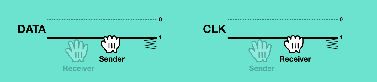
Let’s assume the command has reversed the roles of sender and receiver, so the previous receiver is now the new sender and is still holding DATA, and the previous sender is now the receiver and is still holding CLK. This needs to be reversed.
C: New receiver switches lines
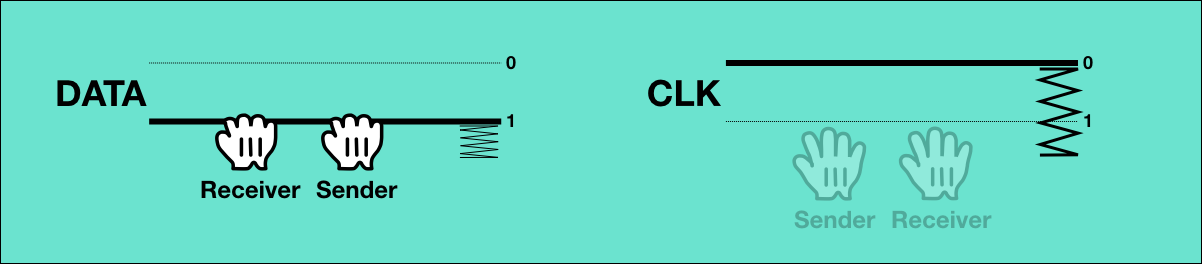
First, the new receiver pulls DATA and lets go of CLK. DATA remains 1, but CLK is now released by both the sender and the receiver and will read back as 0.
D: New sender switches lines
Triggered by CLK being 0, the new sender pulls down CLK and releases DATA. Both lines now read back as 1, which is the initial state for byte transmission, and the correct lines are held by the respective bus participants.
Errors
There are several possible error conditions:
- If at the beginning of a transmission, none of the receivers exist, DATA will not get pulled. After a timeout of 256 µs, this will cause a “DEVICE NOT PRESENT” error. This also applies to the transmission of a command: All devices are required to pull DATA in this case, and if DATA remains at 0, it means that there no devices connected at all.
- There is no way to detect whether the sender exists. When a device is told to send, there are no specified timing requirements about when it has to pull the CLK line.
- If no receiver pulls DATA within 1000 µs at the end of the transmission of a byte (after step 28), a receiver timeout is raised.
- If the sender does not pull CLK within 512 µs after step 3, a sender timeout is raised. The sender hits this timeout on purpose to signal an empty stream.
Timing
Original Design
The design goal of Standard Serial was that its speed would be comparable to IEEE-488. Byte transmission was supposed to be handled by a dedicated shift register, so that the CPU would perform the byte handshake, but the individual bits would be transfered automatically by the hardware. The VIC-20 and the 1540 disk drive, the first devices with the Standard Serial bus, each contained a 6522 VIA I/O controller that supported automatic serial transmission. The hold times for CLK=0 and CLK=1 were 4 µs each5, so a byte could be transfered in 8 µs. This would result in theoretical transmission speeds above 10 KB/sec.
The timing of the CPU-side of the original protocol was very relaxed. Timeouts were on the order of hundreds of µs.
This design never shipped though.
VIC-20
Unfortunately, the Commodore engineers did not account for a bug in the 6522 shift register that was already documented6 by the time the Serial Bus was designed. At the last minute, they increased the hold times to 20 µs, which allowed them to implement the otherwise unchanged protocol in software both in the VIC-20 and the 1540. This reduced the theoretical throughput to 2 KB/sec.
The fact that it was now a pure software protocol also changed the quality of the timing constraints: While the protocol was originally designed to allow any participant to stall in most states, and to only require relatively relaxed timing, the critical byte transmission window now requires the CPU to commit to being undisturbed for 20 µs × 2 × 8 = 320 µs.
C64
The Commodore 64, which was the successor to the VIC-20, contained a 6526 CIA I/O controller that had a working shift register, but Commodore did not enable it for hardware-supported byte transfers, since the accompanying disk drive, the 1541, was not planned to be updated from the buggy 6522 VIA.
To make matter worse, the system architecture of the C64 had the video chip halt the CPU for about 40 µs every ~500 µs, which would make it likely for the CPU to miss the 20 µs window in which a bit was valid. The Commodore engineers decided not to turn off the display during Serial Bus operations (to disable video DMA), as it is done for tape access.
In theory, it would be possible to fit the 320 µs to transmit a byte within the predictable 500 µs window between DMAs, but it is the sender that decides when to start the transmission of a byte and controls the actual transmission speed.
So the specification of the protocol was changed to increase the hold time by 40 µs, to 60 µs – but only in some cases: It was acknowledged that computers like the C64 might need more time to see a bit on the bus, but devices were still required to make the 20 µs window. Therefore, all devices use 60 µs hold times when sending data, but controllers can use 20 µs7. This reduces the theoretical throughput from devices to controllers to below 1 KB/sec.
In practice, the Serial Bus implementation in the system software of the VIC-20 was still standards compliant. The 1540 disk drive was updated as the 1541 with the new (slower) timing, but an option to change the bus speed to VIC-20 mode (Commodore DOS command “UI-”). Printers and plotters designed for the VIC-20 did not have to be updated to work with the C64, because they only received data and never sent any.
SRQ
There is one more data wire in the cable: The SRQ (“Service Request”) line. In the IEEE-488 protocol, SRQ is basically an interrupt line that allows any device to signal the controller that it would like its attention. The controller would then use layer 3 commands to find out which device sent the request and handle it accordingly. The PET has the line connected and makes it available to software, but the KERNAL driver does not support it, and no Commodore devices make use of it. The Serial Bus inherited the SRQ line, but again, while it is connected and accessible by software (VIC-20, C64), neither the KERNAL nor any devices support it. On the Plus/4, the line is no longer connected to anything.
On the C128, the wire was reused in an unrelated way for the Fast Serial protocol.
Discussion
While the open collector property of CLK and DATA allows several devices to signal their state over a single wire, the bus is nevertheless severely constrained in terms of wires. While the parallel IEEE-488 bus has practically no timing requirements, the serial version requires strict timing in most states.
Between Bytes Bug
There is one bug in the specification that is caused by these timing complexities. After all bits of a byte have been sent, all receivers are required to pull DATA within 1000 µs to signal they are not ready for the next byte. All receivers share the same DATA line, and it will read back as soon as any receiver pulls it. So once the first receiver pulls it, the sender signals it is ready to send the next byte after a delay of 100 µs (“between bytes time”). It then waits for DATA to be 0 again, which can happen immediately once the same receiver releases it. Now, in the middle of the transmission of the byte, another receiver wakes up and pulls DATA, still within the legal 1000 µs, destroying the transmission.
In the original IEEE-4888 protocol, there is the dedicated NRFD (“not ready for data”) line that is pulled by all receivers before accepting the data, so all receivers have to release it before transmission can continue. On the Serial Bus, both the CLK and the DATA line are operated by the sender until the completion of the byte transmission, so there is no way for the receivers to communicate anything before that.
The bug would be fixed by reducing the allowed time to pull DATA to 100 µs, the same as the “between bytes time”. In practice, this is not an issue though, because one-to-many communcation is extremely rarely used, and because Serial Bus devices tend to respond within 100 µs anyway.
Data Valid Window vs. CLK/DATA
While the specification change between the VIC-20 and the C64 had to be minimal to keep as much compatibility as possible, the change between the original design, which never shipped, and the VIC-20 had no compatibility requirements. On the VIC-20, the transmission of a byte through CLK and DATA followed the protocol of the 6522 VIA shift register, even though it was implemented in software.
Instead, a modified protocol could have sent one bit on every edge of CLK, doubling the data rate. They could also have sent two bits at a time, one in CLK and one in DATA with a strict timing of 20 µs per bit. This would only have required the receiver to commit to a 80 µs window of being able to receive data with a timing accuracy below 20 µs. This would have broken horribly on the C64 though, which cannot commit to this, but alternative protocols including JiffyDOS (part 6 of this series), are based on this strategy.
The advantage of keeping the 6522 VIA shift register protocol was that they would be able to use a working shift register in later devices and just switch to the original timing – optionally, if all devices supported it. The Fast Serial protocol of the C128 does indeed use the shift register of the 6526 CIA I/O controller, but does not use the same CLK/DATA protocol with it.
Next Up
Part 5 of the series of articles on the Commodore Peripheral Bus family will cover layers 1 and 2 of the TCBM protocol as used on the TED series of computers (C16, C116, Plus/4).
This article series is an Open Source project. Corrections, clarifications and additions are highly appreciated. I will regularly update the articles from the repository at https://github.com/mist64/cbmbus_doc.
References
- How The VIC/64 Serial Bus Works by Jim Butterfield
- IEC disected by J. Derogee
- Related to, but not the same as, and often confused with “Burst Mode”.↩
- The implementation file in the Commodore 64 KERNAL source is “
serial4.0”. The context of the version number is unknown, since no other versions have appeared. On the TED and the C128, the file is just called “serial.src”.↩ - The specification states calls this action “data accepted”, which makes no sense. “Data accepted” would mean that the sender can now remove the data from the bus, because all receivers have seen it. But at this point, there is no more data on the bus, there is nothing for the sender to remove, and the positive logic means that any receiver would be able to accept the data for all receivers.↩
- IEEE-488 also signals this during the last byte, by pulling the dedicated EOI line to 1 while the data is valid.↩
- It is not documented what the planned hold times were. The software implementation of the VIC-20 uses 20 µs, and Jim Butterfield’s “A brief history of the IEC-bus” states that this was “5 to 6” times slower than planned. 5 times slower would point to a planned hold time of 4 µs, and 6 times slower might account for the software implementation taking an extra cycle here and there. The 6522 documentation doesn’t seem to say anything about the minimum cycle time for the shift register, but the docs of the successor, the 6526 CIA, state a minimum clock of Phi0/4, i.e. a hold time of 4 µs.↩
- Garth Wilson posted a workaround in December 2000.↩
- In practice, the C64 holds CLK for 42 µs and the 1541 for 74 µs, for example.↩
“but Commodore did not enable it for hardware-supported byte transfers, since the accompanying disk drive, the 1541, was not planned to be updated from the buggy 6522 VIA.”
Bob Russell told it differently in 2006 (drive talk is from 13:30, c64 fast serial is at 19:00)
https://www.youtube.com/watch?v=km701Z3KQiI
In summary fast serial was planned for the c64, but commodore japan broke it when they did the pcb layout for production. It wasn’t noticed in the US because the software work hadn’t been done.
Yash Terakura talks at 33:30 about how vic20 / c64 production design was done in japan, with more slow serial talk at 40:00 where Benny Pruden mentions they had added fast serial to the 1541 pcb.
https://www.youtube.com/watch?v=OEQMrU7BxEs
You can perform your own modification to put it back on the c64. https://a1bert.kapsi.fi/Dev/burst/ & use 1571/1581 drives quickly.
Modifying a 1541 is harder, but it should be possible as there is a simple circuit online to fix the 6522 bug in hardware (IIRC you have to make sure the 1mhz clock and the serial data clock don’t change state at the same time).
The data bit polarity in step 5 is incorrect. A 0 bit is transmitted as 0V level and a 1-bit as 5V(ish) level on the bus, see for example E965-E976 in the 1541 ROM.
It would make much more sense to swap 0 and 1 everywhere on this page, changing it to the usual TTL convention. Just because it is an open collector bus does not mean that the voltage-to-bit mapping has to be inverted – I2C doesn’t do that either.
@Ingo: Please correct me if I’m wrong, but to my understanding an “inverting buffer IC” between the I/O chip and the connector reverses the outgoing signals. Setting the DATA-OUT bit in the I/O register to 1 (to transmit a 1 bit) also sets the respective output pin of the I/O chip to 1 (5 V), but due to the inverting this results in a LOW level on the bus. On the receiver’s side, this will be reversed back by similar IC, so the “chip logic” (if you like) does not notice this reversed bus logic. You might identify the “inverting buffer ICs” as 7406 or 74LS04 on any schematic diagram near the connectors.
Hello Michael and thank you for your work, great source of information and inspiration. Thanks to this page, I am implementing a virtual IEC device in my emulator. However, I have a problem with the EOI part. It seems to me that there is an error in the description of the protocol.
“To indicate the end of the stream, the sender delays step 4 by at least 200 µs.”
I observe that the EOI is communicated not by delaying the CLK (invalid data) trigger by 200µs but rather by not triggering CLK at all but by letting the receivers go in timeout. The receivers wait at least 200µs for the invalid data signal. If they do not receive it, then they start their ACK sequence. It is after this sequence (pull DATA, release DATA), that step 4 resumes. Here are the Kernal lines corresponding to this EOI sequence :
.,ED4C 24 A3 BIT $A3 BIT R2D2 ;EOI FLAG TEST
(Test if the next byte to send is the last of stream)
ED4E 10 0A BPL $ED5A BPL NOEOI
(If not the last byte, then jump to step 4 (invalid data))
.ED50 20 A9 EE JSR $EEA9 ISR02 JSR DEBPIA ;WAIT FOR DATA TO GO HIGH
.ED53 90 FB BCC $ED50 BCC ISR02
(Else loop until one receiver pulls Clk)
.ED55 20 A9 EE JSR $EEA9 ISR03 JSR DEBPIA ;WAIT FOR DATA TO GO LOW
.ED58 B0 FB BCS $ED55
(Then loop until all receivers release Clk)
Then the controler goes on with step 4…
A fantastic series of articles Michael, thank you for your dedication and work. The whole Commodore KERNAL, IEEE 488, and IEC history is just fascinating tom me!
In my observations CLK is not pulled low again until after EOI ACK by the talker.
Your visualization of the protocol has helped me a great deal.
Thanks Michael.
Ok… more to add. When the C64 is the TALKER on the IEC Serial bus it waits for the EOI Ack to complete before pulling the CLK line low and continuing.
When a 1541 is the TALKER on the IEC serial bus it pulls the CLK line low before the C64 completes the EOI Ack. It still waits for the DATA line to be released before continuing.
I found this interesting.
Is it possible to start an ATN command byte, and then wait >512us (possibly much greater), and then send the command long after the receivers have ack’d?
I’m noodling on a project that would need non-blocking access to the serial port by giving up on a transfer when it’s taken too long — and near as I can tell, receivers (reasonably) being able to delay indefinitely on a ATN byte is the one thing keeping that from working. If the computer could be just as unreasonable, since EOI doesn’t count on an ATN, it could make this work.