In the series about the variants of the Commodore Peripheral Bus family, this article covers the common layer 3: the bus arbitration layer with the TALK/LISTEN protocol.
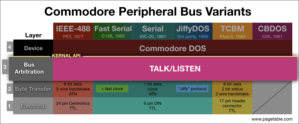
The variants of the Commodore Peripheral Bus family have some very different connectors and byte transfer protocols (layers 1 and 2), but they all share layers 3 and 4 of the protocol stack. This article on layer 3 is therefore valid for all Commodore 8 bit computers, no matter whether they use IEEE-488, Serial, TCBM or CBDOS on the underlying layers.
All variants of layer 2, the layer below, provide:
- the transmission of byte streams from any bus participant to any set of bus participants
- the transmission of “command” byte streams from the designated “contoller” (the computer) to all other bus participants
Layer 3, which is based on the IEEE-488 standard, provides interruptable communication between “channels” of different devices.
NOTE: I am releasing one part every week, at which time links will be added to the bullet points below. The articles will also be announced on my Twitter account @pagetable and my Mastodon account @pagetable@mastodon.social.
- Part 0: Overview and Introduction
- Part 1: IEEE-488 [PET/CBM Series; 1977]
- Part 2: The TALK/LISTEN Layer ← this article
- Part 3: The Commodore DOS Layer
- Part 4: Standard Serial (IEC) [VIC-20, C64; 1981]
- Part 5: TCBM [C16, C116, Plus/4; 1984]
- Part 6: JiffyDOS [1985] (coming soon)
- Part 7: Fast Serial [C128; 1986] (coming soon)
- Part 8: CBDOS [C65; 1991] (coming soon)
Controller
Layer 2 allows everyone on the bus to talk to everyone else – but there is no mechanism in place for who is sending or receiving data at what time. The primary feature of layer 3 is controlling exactly this.
One bus participant needs to be the designated controller – this is always the computer. It sends command byte streams to all other bus participants, the devices.
Primary Address
The controller needs to be able to address an individual device. Every device on the bus has a primary addresses from 0 to 30. The controller itself does not have an address.
Primary addresses (aka device numbers) are usually assigned through DIP switches (e.g. Commodore 1541-II: 8-11) or by cutting a trace (e.g. original Commodore 1541: 8 or 9).
On Commodore systems, there is a convention for device numbers:
| # | type |
|---|---|
| 4, 5 | printers |
| 6, 7 | plotters |
| 8 – 11 | disk drives, hard disks |
| 12 – 30 | some third party drives, misc. |
Devices 0-3 are reserved for devices outside the Commodore Peripheral Bus, which share the same primary address space in the KERNAL’s Channel I/O API as well as in BASIC.
Note that this is just a convention and hints towards what protocol is used on layer 4, the layer above. On layer 3, neither computers nor devices care about this convention1.
Talkers and Listeners
In order to tell devices that they are now supposed to send or receive data, the controller hands out two roles: “talker” and “listener”.
- A talker is sending a byte stream.
- A listener is receiving a byte stream.
Any device can be either a talker, a listener, or passive. There can only be one talker at a time, and there has to be at least one listener.
The controller itself can also be the talker or a listener. In fact, in the most common cases, the controller is either the talker, with a disk drive as the single listener (e.g. writing a file), or the controller is the single listener, with a disk drive as the talker (e.g. reading a file).
TALK and LISTEN commands
To hand out the talker and listener roles to devices and to withdraw them, the controller sends a command byte stream containing one of the following codes:
| command | description | effect |
|---|---|---|
0x20 + pa |
LISTEN |
device pa becomes listener; ignored by other devices |
0x3F |
UNLISTEN |
all devices stop listening |
0x40 + pa |
TALK |
device pa becomes talker; all other devices stop talking |
0x5F |
UNTALK |
all devices stop talking |
For the LISTEN and TALK commands, the primary address of the device gets added to the code. The UNLISTEN and UNTALK commands correspond to the LISTEN and TALK with a primary address of 31. This is what restricts primary addresses to the range of 0-30.
All devices receive and interpret command bytes, so for example, a TALK command for device 8 will implicitly cause device 9 to stop talking, in case it currently was a talker.
A role change of the controller itself is not communicated through commands, since the controller already knows this (after all, it is the one making the decision), and the devices do not need to know.
Secondary Address
The designers of IEEE-488 felt that a device should have multiple functions or contexts, or that multiple actual devices could be sitting behind a single primary address. Each of these channels can be addressed using a secondary address from 0 to 31.
A command specifying the secondary address can optionally be sent after a TALK or UNTALK command.
| command | description | effect |
|---|---|---|
0x60 + sa |
SECOND |
last addressed device selects channel sa |
The interpretation of the secondary address is up to the device and specified on layer 4. In practice, they are interpreted as options or flags (e.g. for printers) or different file contexts (e.g. for disk drives).
Devices are free to ignore the secondary address or only honor certain bits of it. Commodore disk drives, for example, ignore bit #4, so channels 16-31 are the same as channels 0-15.
Examples
Here are some examples for receiving, sending and copying, as well as for a controller-less connection.
Receiving Data from a Device
If the controller wants to read a byte stream from device 8, channel 2, it sends this:
| command | description |
|---|---|
0x48 |
TALK 8 |
0x62 |
SECOND 2 |
The controller then becomes a listener and reads bytes from the bus. If the controller has had enough data, it can send this:
| command | description |
|---|---|
0x5F |
UNTALK |
The current talker will then release the bus. The controller can resume the transmission of data from the channel by sending the same TALK/SECOND commands again.
The controller has to stop receiving bytes onces it encounters the end of the stream (EOI). There is no need to send UNTALK in this case, since the talker will automatically release the bus.
Sending Data to a Device
Here is an example that sends a byte stream to device 4, channel 7:
| command | description |
|---|---|
0x24 |
LISTEN 4 |
0x67 |
SECOND 7 |
The controller then sends the byte stream. Like in the case of receiving data, the controller can pause transmission like this:
| command | description |
|---|---|
0x3F |
UNLISTEN |
and resume it using the same LISTEN/SECOND combination2. If the controller has reached the end of its byte stream, it signals EOI. Again, there is no need to send UNLISTEN in this case.
Manually Copying Data Between Devices
The following example has the controller manually copy a byte stream from device 8, channel 2 (a disk drive) to device 4 (a printer). First, it tells device 8, channel 2 to talk:
| command | description |
|---|---|
0x48 |
TALK 8 |
0x62 |
SECOND 2 |
Now the controller reads a byte from the bus. It then instructs the talker to stop talking and tells device 4 to listen:
| command | description |
|---|---|
0x5F |
UNTALK |
0x24 |
LISTEN 4 |
In this case, there is no secondary address for device 4, so the device picks its default channel. The controller then sends the byte it just read back onto the bus and tells device 4 to stop listening.
| command | description |
|---|---|
0x3F |
UNLISTEN |
Now it can repeat the whole procedure from the start, until the read operation signals the end of the stream.
Obviously this is slow, because it transmits 7 bytes for every byte of payload. A more optimized version would read and write something like 256 bytes at a time.
Having Devices Talk to Each Other
But devices can also talk directly to each other, without the controller’s involvement. This way, data only travels over the bus once.
This command byte stream will instruct devices 4 and 5 (two printers) to listen and device 8, channel 2 (a disk drive) to talk. After the transmission of the command, device 8 will automonously send whatever data it can provide from channel 2 to devices 4 and 5.
| command | description |
|---|---|
0x24 |
LISTEN 4 |
0x25 |
LISTEN 5 |
0x48 |
TALK 8 |
0x62 |
SECOND 2 |
Device 8 now starts sending bytes, and devices 4 and 5 will receive them. The layer 2 protocol makes sure that the listeners will adapt to the talker’s speed and wait patiently when it stalls (e.g. the disk drive has to read a new sector), and the talker will adapt to the speed of the slowest listener and wait patiently when any of them stalls (e.g. when the printer has to feed the paper).
The controller can interrupt the transmission at any time by sending new commands. In can, for example, read from a different channel of the disk drive, and then resume the print job by sending the above command sequence again.
If the controller wants to know when the transmission is finished, it will have to be a listener as well and detect the end of the stream (EOI).
Named Channels (OPEN/CLOSE)
When Commodore chose IEEE-488 as the protocol stack for the PET, they felt that a numeric secondary address from 0 to 31 was not expressive enough for the different contexts of e.g. a disk drive, so they added named channels.
The controller can associate a secondary address with a name, and later dissociate it again. A name is a byte stream of arbitrary length (including zero bytes) and usually the PETSCII encoding is implied. Only secondary addresses in the range of 0-15 can be associated with a name, 16-31 cannot.
| command | description | effect |
|---|---|---|
0xE0 + sa |
CLOSE |
dissociate sa from its name |
0xF0 + sa |
OPEN |
associate sa with a name |
Both commands have to be prefixed with a LISTEN command to address the correct device. An OPEN command sequence that associates a name with channel 2 on device 8 looks like this:
| command | description |
|---|---|
0x28 |
LISTEN 8 |
0xF2 |
OPEN 2 |
The controller now sends the name of the channel, followed by UNLISTEN:
| command | description |
|---|---|
0x3F |
UNLISTEN |
Unlike regular data transmissions, where the controller can pause and resume the stream using UNLISTEN/LISTEN, the name of the channel has to be sent in one go. The end of the name is indicated by the UNLISTEN command, not by EOI.
The device can indicate an error associating the channel with the name3 using an error condition on layer 2.
Dissociating a channel from a name is done using the sequence LISTEN/CLOSE/UNLISTEN, like in this example:
| command | description |
|---|---|
0x28 |
LISTEN 8 |
0xE2 |
CLOSE 2 |
0x3F |
UNLISTEN |
Compatibility with IEEE-488
The bus arbitration layer of the Commodore Peripheral Bus is based on and mostly compatible with the IEEE-488 specification, but with additions and some missing features.
Added Features
As mentioned earlier, OPEN and CLOSE are a Commodore extension. Commodore added it in a clever way that didn’t clash with any features of the IEEE-488 specification.
In IEEE-488, all command codes have the same bit layout:
| bit | description |
|---|---|
| 7 | ignored |
| 6 – 5 | command code |
| 4 – 0 | primary or secondary address |
This allows for 4 command codes, 30 primary addresses and 31 secondary addresses. This is the complete command table on Commodore devices:
| command | binary | description |
|---|---|---|
0x00 + cmd |
000nnnnn |
(global command) |
0x20 + pa |
001nnnnn |
LISTEN |
0x40 + pa |
010nnnnn |
TALK |
0x60 + sa |
011nnnnn |
SECOND |
0xE0 + sa |
1110nnnn |
CLOSE |
0xF0 + sa |
1111nnnn |
OPEN |
The codes for CLOSE (0xE0) and OPEN (0xF0) reuse the code for SECOND (0x60), but with bit #7 set. To devices that don’t understand the Commodore OPEN/CLOSE protocol, these commands look like SECOND and will be ignored, since they are sent after a LISTEN command that targets a different device.
Bit 4 of the command, the most significant bit of the secondary address, is used to distinguish between OPEN and CLOSE, which is why it is only possible to associate 16 secondary addresses with a name.
Missing Features
There is one unsupported entry in the table above: The command code of ‘000’ has a sub-code in bits 0-4, specifying a global command to all devices. These control features like the handling of “SRQ” Service Requests and multiple controller support. The system software of Commodore computers does not support any of these features, but on a PET/CBM with a physical IEEE-488 port, support could be added by user software.
APIs
The KERNAL operating system of all Commodore 8 bit computers since the VIC-20 (i.e. also the C64/C128/C65, the Plus/4 Series and the CBM-II) supports two sets of APIs to talk to devices on the Commodore Peripheral Bus. The built-in BASIC interpreter also has instructions to handle the bus.
KERNAL IEEE API
The “IEEE” API is a set of low-level calls. It allows using primary addresses 0-3, which are not available through the high-level APIs.
| address | name | description | arguments |
|---|---|---|---|
$FFB1 |
LISTEN |
Send LISTEN command |
A = pa |
$FFAE |
UNLSN |
Send UNLISTEN command |
|
$FF93 |
SECOND |
Send LISTEN secondary address |
A = 0x60 + sa |
$FFB4 |
TALK |
Send TALK command |
A = pa |
$FFAB |
UNTLK |
Send UNTALK command |
|
$FF96 |
TKSA |
Send TALK secondary address |
A = 0x60 + sa |
$FFA5 |
ACPTR |
Read byte from serial bus | byte → A |
$FFA8 |
CIOUT |
Send byte to serial bus | A = byte |
$FFA2 |
SETTMO |
Set timeout | A = { 0x00 | 0x80 } |
Note the difference between SECOND to send a secondary address after LISTEN, and TKSA to send a secondary address after TALK. Layer 2 generally needs this distinction to get the bus into the correct state afterwards.
All calls deal with layer 3 functionality, except for SETTMO, which controls a layer 2 setting. The IEEE-488 layer 2 on the PET/CBM has an option to enable (A = 0x00, default) or disable (A = 0x80) timeouts. Timeouts are required to allow the talker to communicate an error when opening a named channel, but they can break IEEE-488 devices not designed for the PET. The call also exists on all other Commodore 8 bit computers, but has no effect, with the exception of a C64 with an added IEEE-488 cartridge.
KERNAL Channel I/O API
The KERNAL’s Channel I/O API is higher-level and not specific to the Commodore Peripheral Bus. Devices 0-3 will target the keyboard, tape, RS-232 (PET: tape #2) and the screen. This API does not support multiple listeners or controller-less transmissions (but it can be combined with the low-level API for this).
| address | name | description | arguments |
|---|---|---|---|
$FFB7 |
READST |
Read I/O status word | st → A |
$FFBA |
SETLFS |
Set logical, first, and second addresses | A = lfn, X = pa, Y = sa |
$FFBD |
SETNAM |
Set file name | A = len, X/Y = name |
$FFC0 |
OPEN |
Open a logical file | |
$FFC3 |
CLOSE |
Close a specified logical file | A = lfn |
$FFC6 |
CHKIN |
Open channel for input | X = lfn |
$FFC9 |
CHKOUT |
Open channel for output | X = lfn |
$FFCC |
CLRCHN |
Close input and output channels | |
$FFCF |
CHRIN |
Input character from channel | byte → A |
$FFD2 |
CHROUT |
Output character to channel | A = byte |
$FFE7 |
CLALL |
Close all channels and files |
Channel I/O allows up to 10 logical files open at the same time, across all devices. A logical file is addressed by a user-selected logical file number (0-127). To open a logical file, the logical file number and device’s primary and secondary addresses (255 = none) have to be set using SETLFS, the name has to be set using SETNAM, and OPEN hast to be called.
OPEN with a filename will send the LISTEN/OPEN/filename/UNLISTEN sequence, associating the name with the secondary address. OPEN without a filename will not send anything on the bus, but will remember the secondary address for later operations.
Similary, CLOSE on a file with a filename will send the LISTEN/CLOSE/UNLISTEN sequence, and otherwise, CLOSE will not send anything on the bus.
The current input and/or output has to be globally selected using CHKIN, which will send TALK, and CHKOUT, which will send LISTEN. Both are followed by SECOND, if a secondary address was set. CLRCHN resets the current input and output channels and sends UNTALK or UNLISTEN.
With CHKIN/CHKOUT set up to talk on the Commodore Peripheral Bus, CHRIN and CHROUT will just be forwarded to the low-level calls ACPTR and CIOUT.
BASIC API
The complete channel I/O API is directly accessible through BASIC instructions:
| command | description |
|---|---|
OPEN lfn, pa [, sa [, name]] |
open logical file |
CLOSE lfn |
close logical file |
GET# lfn, var |
read character |
INPUT# lfn, var |
read string/int/float |
PRINT# lfn, var [, …] |
write string/int/float |
CMD lfn |
redirect standard out |
Note that every GET#, INPUT# and PRINT# instruction will go through a TALK/UNTALK or LISTEN/UNLISTEN sequence.
Next Up
Part 3 of the series of articles on the Commodore Peripheral Bus family will cover Layer 4: Commodore DOS.
This article series is an Open Source project. Corrections, clarifications and additions are highly appreciated. I will regularly update the articles from the repository at https://github.com/mist64/cbmbus_doc.
References
- Fisher, E. R., & Jensen, C. W.: PET and the IEEE 488 Bus (GPIB). Berkeley, Calif: OSBORNE/McGraw-Hill, 1982. ISBN 0-931988-31-4.
- Keller, R. & Hurling H.: IEC-Bus – im Labor bewährt. in: c’t Magazin für Computer und Technik, 9/87, p. 187-192. ISSN 0724-8679.
- Derogee, J. & Butterfield, J.: IEC disected. 2008.
- Commodore 64 Programmer’s Reference Guide. [S.l.]: Commodore Business Machines, 1987. ISBN: 0672220563
- cbmsrc – Original source code of various Commodore computers and peripherals
-
It is possible to change the primary address of a Commodore 1541 using a Commodore DOS (layer 4) command, with
oas the old andnas the new address:o=8:n=4:oP15,o,15:pR15,"m-w";cH(119);cH(0);cH(2);cH(n+32)+cH(n+64):clO15
It is no problem to change the primary address to 4, the default address of the printer, and still interact with it using BASIC commands for disk access:load"$",4↩ -
Commodore DOS breaks this convention in one case: When a disk drive receives a command string on channel 15, it will execute it as soon as there is an
UNLISTENevent, as opposed to only triggering onEOI.↩ -
For disk drives, this happens when layer 4 decides that a file was not found or there was no disk in the drive, for example.↩
Excellent article—exactly what I was looking for. Thanks!
Great reference article.
In the article, however, it says “A command specifying the secondary address can optionally be sent after a TALK or UNTALK command.”
I believe this is a mistake and should say “… after a TALK or LISTEN command”.