The 1551 is the weird outlier in the family of Commodore disk drives: It is the only drive using the “TCBM” bus instead of Serial or IEEE-488. And what’s even weirder? 1541 and 1570 drives converted into 1551s!
The first Commodore disk drives for the PET were using the industry-standard parallel IEEE-488 bus. For cost reasons, Commodore switched to a custom serial version of the bus with the VIC-20 and the C64. But serial was slow, and IEEE-488 was expensive. TCBM was supposed to be the compromise. There was no connector on the drive side, and the computer side was a cartridge (“paddle”) with the I/O chip – which was shipped with the drive instead of the computer, to keep the cost of the computer low.
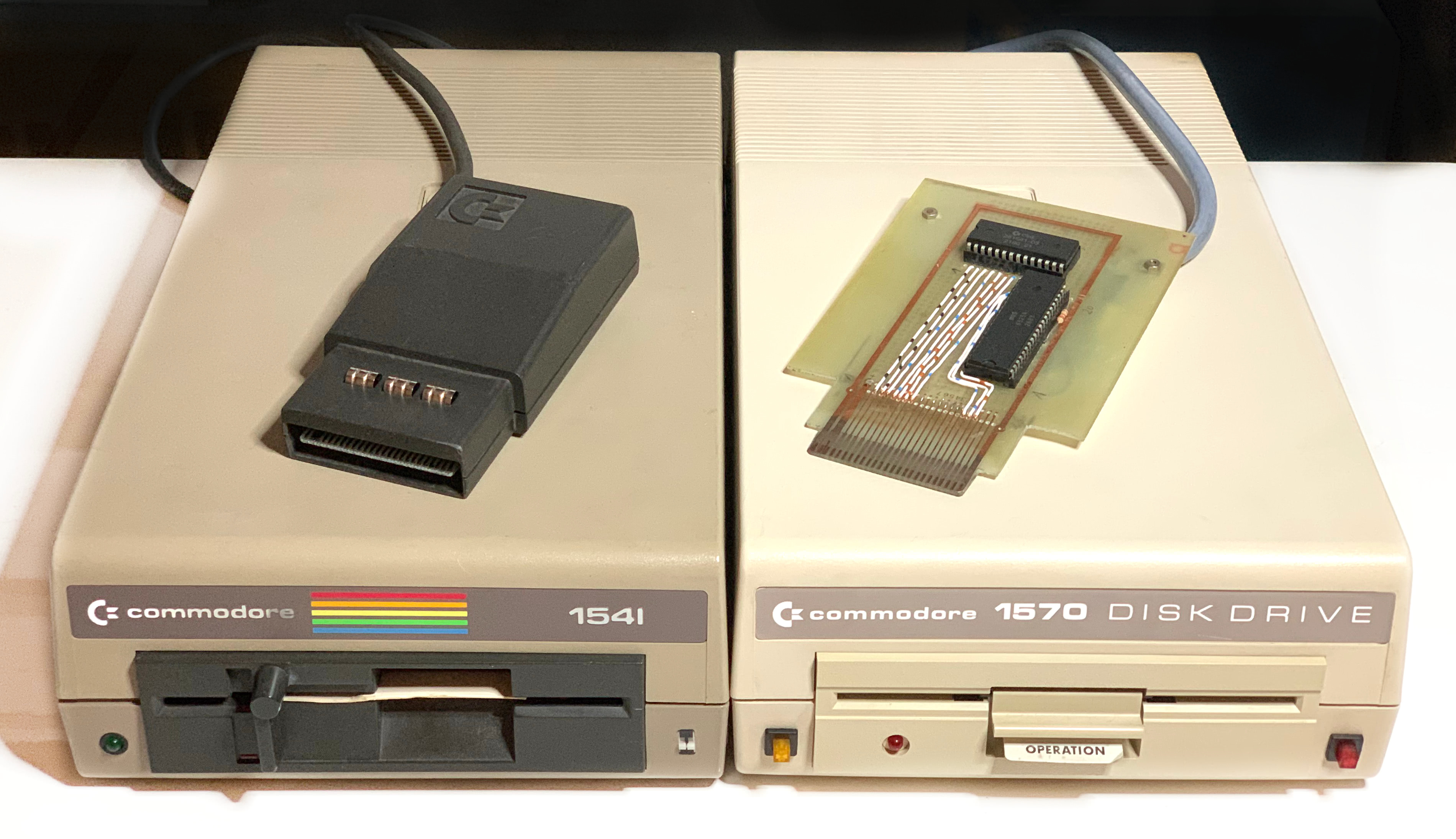
Pictures
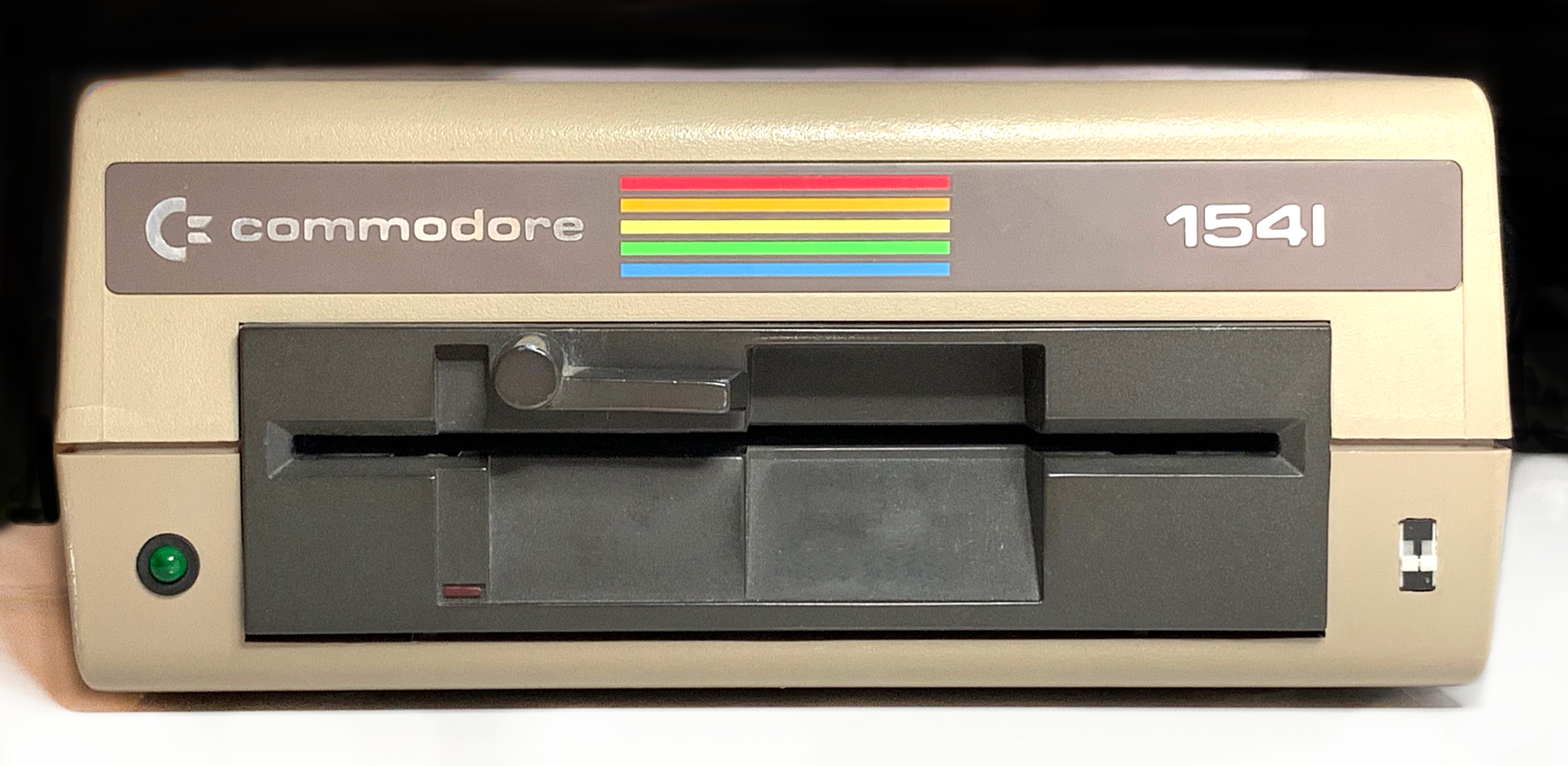
The modded 1541 looks just like a 1541 from the front, except for the device 8/9 switch – but many 1541 drives had that added.
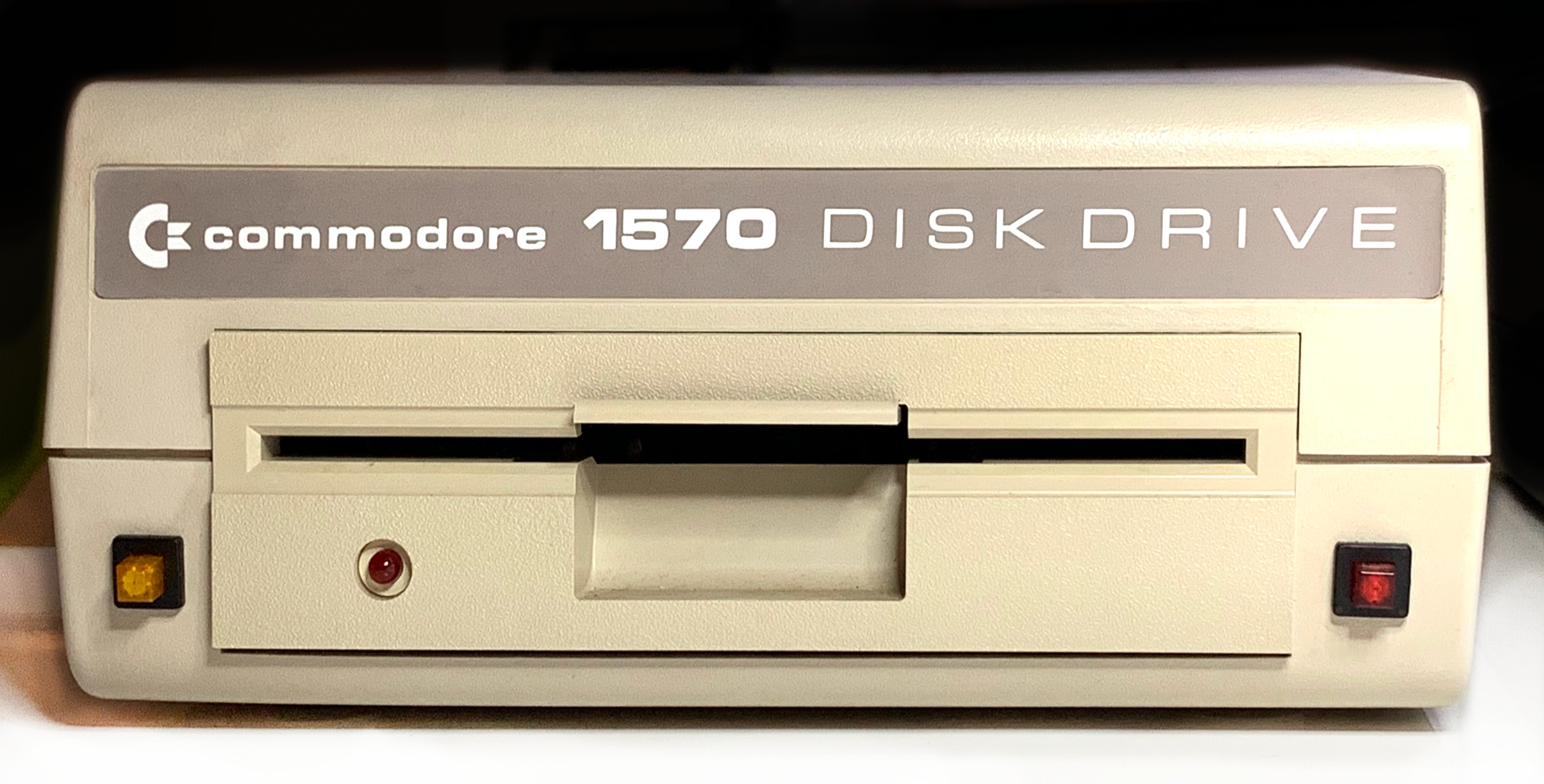
The 1570 has the power LED converted into a reset button with a power LED, and on the right, there is an added device 8/9 toggle button with an LED indicating the current device number.
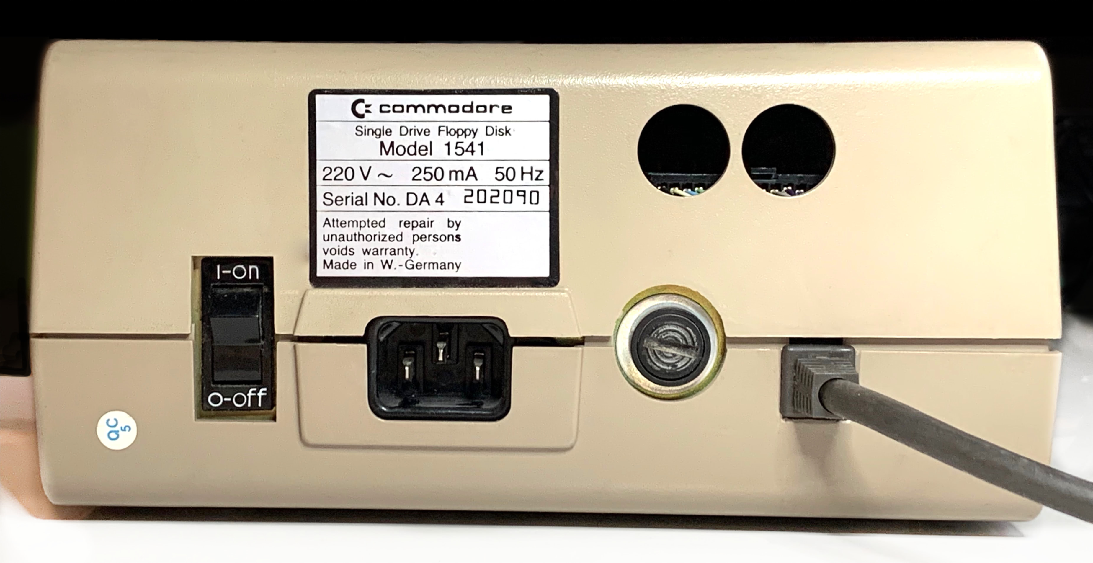
On the back, the 1541 has two holes where the serial ports were, and the added 1551 paddle cable.
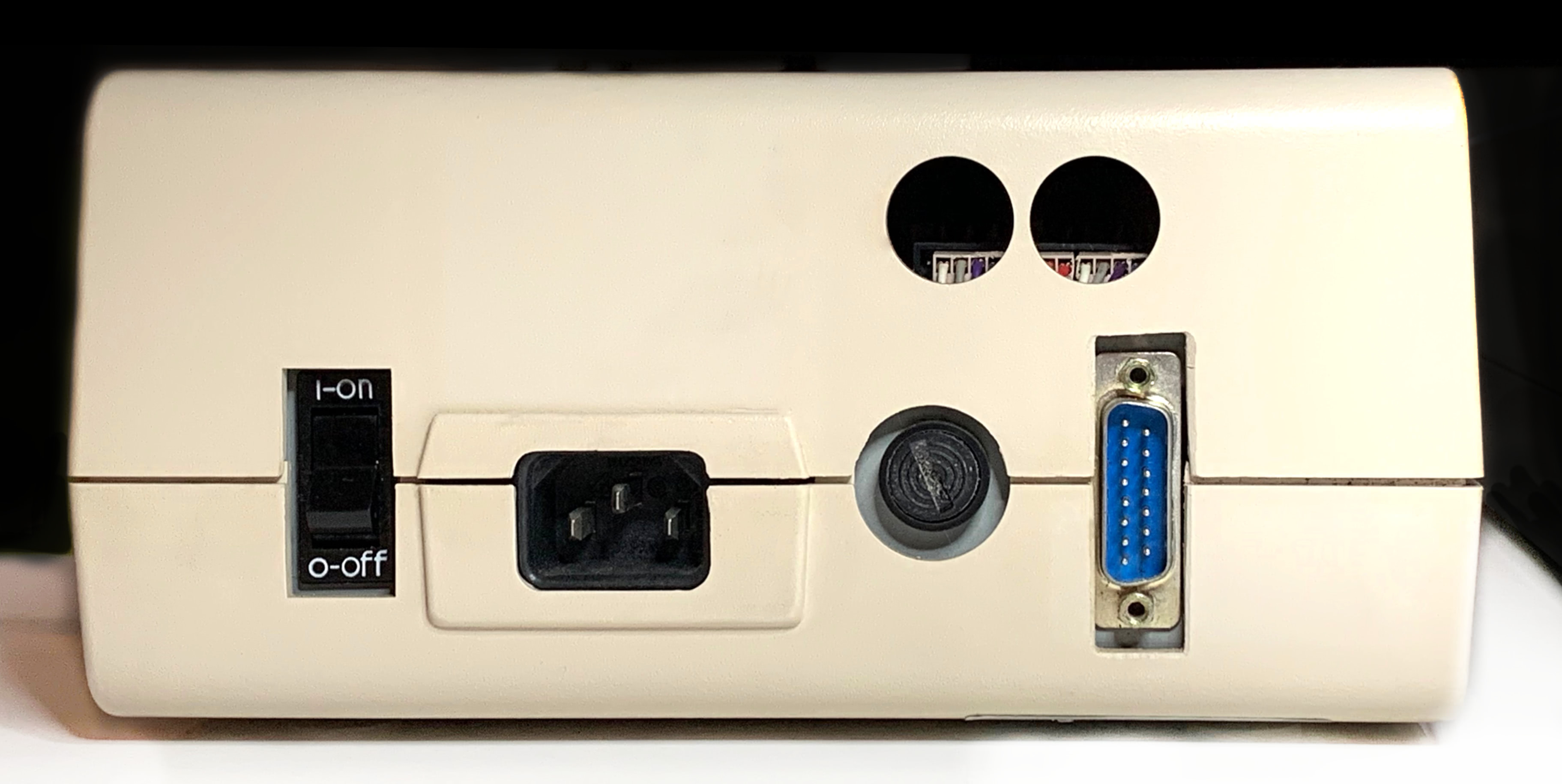
The 1570 also has empty holes, but it uses a DB15 connector for the paddle.
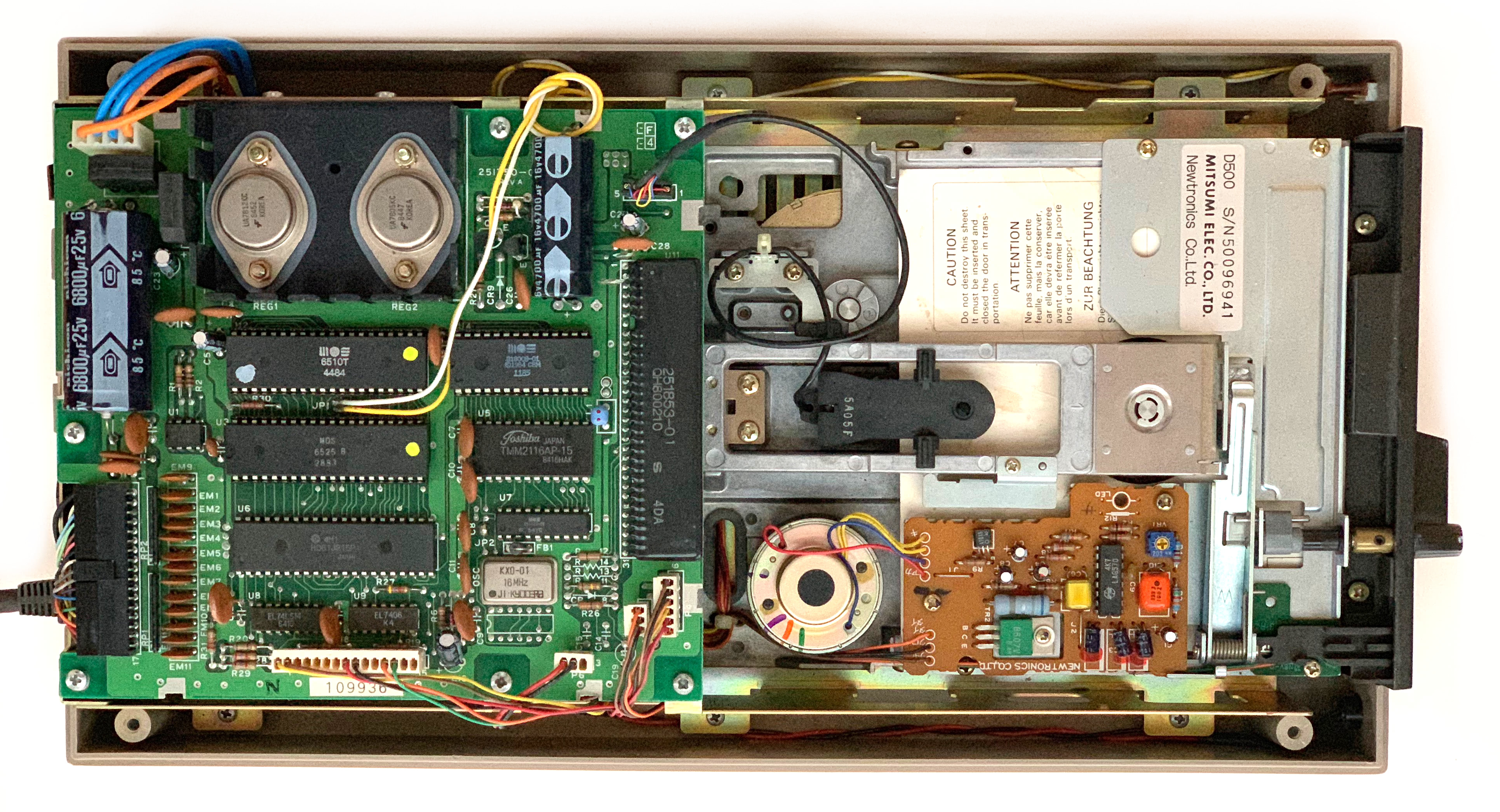
The mechanics of the 1541 are unchanged, but the board has been replaced with a 1551 board.
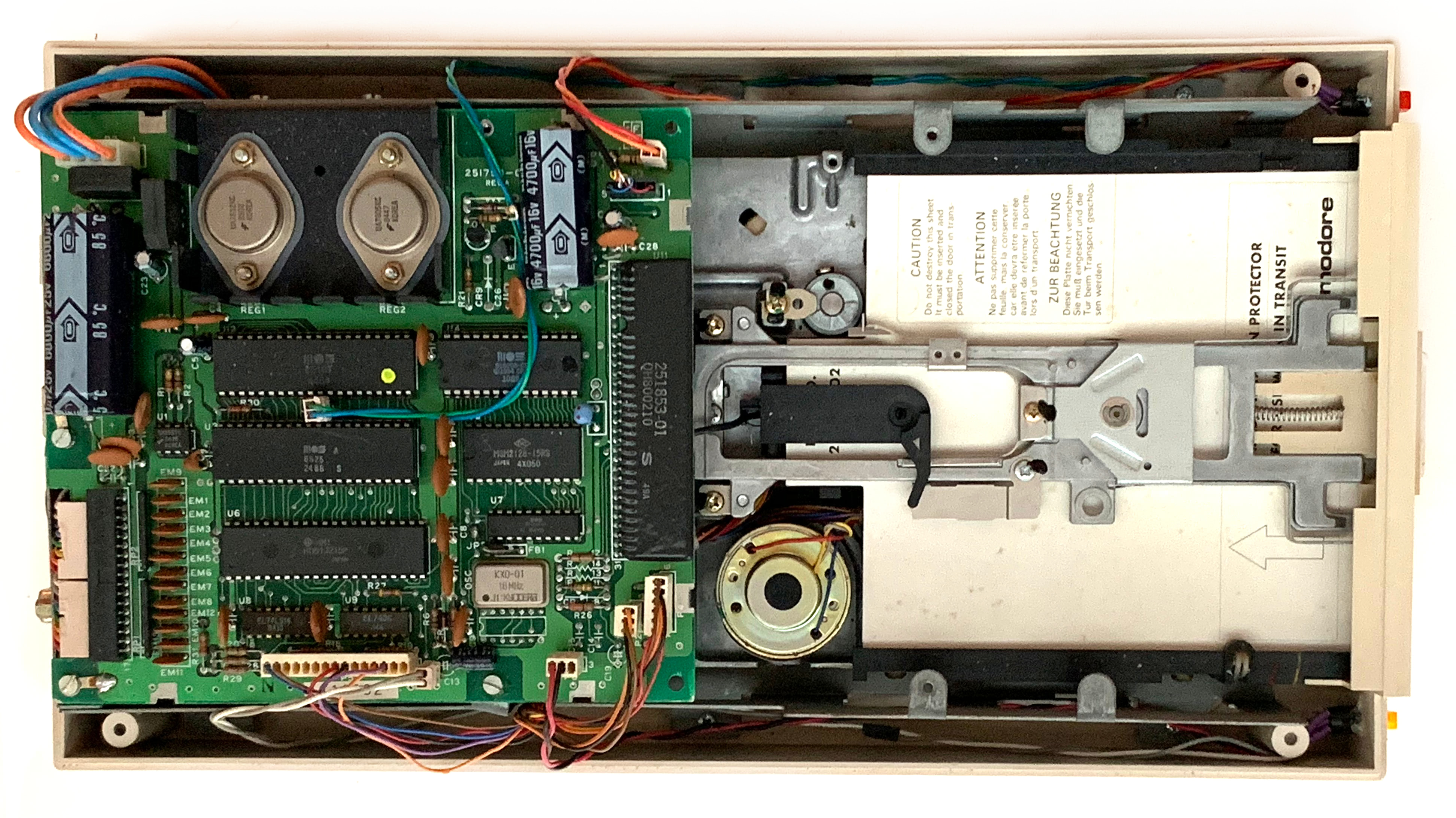
Same on the 1570.
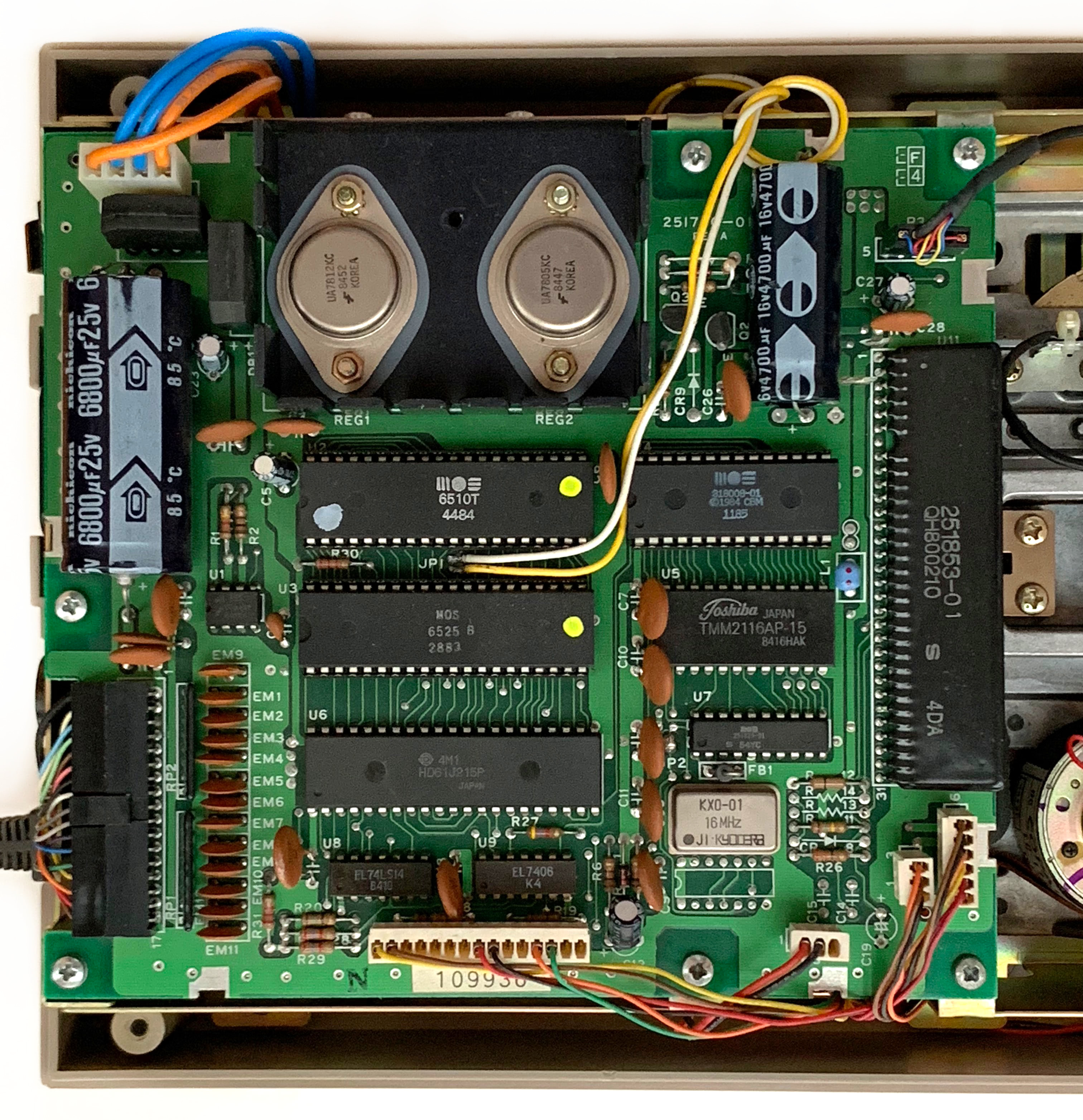
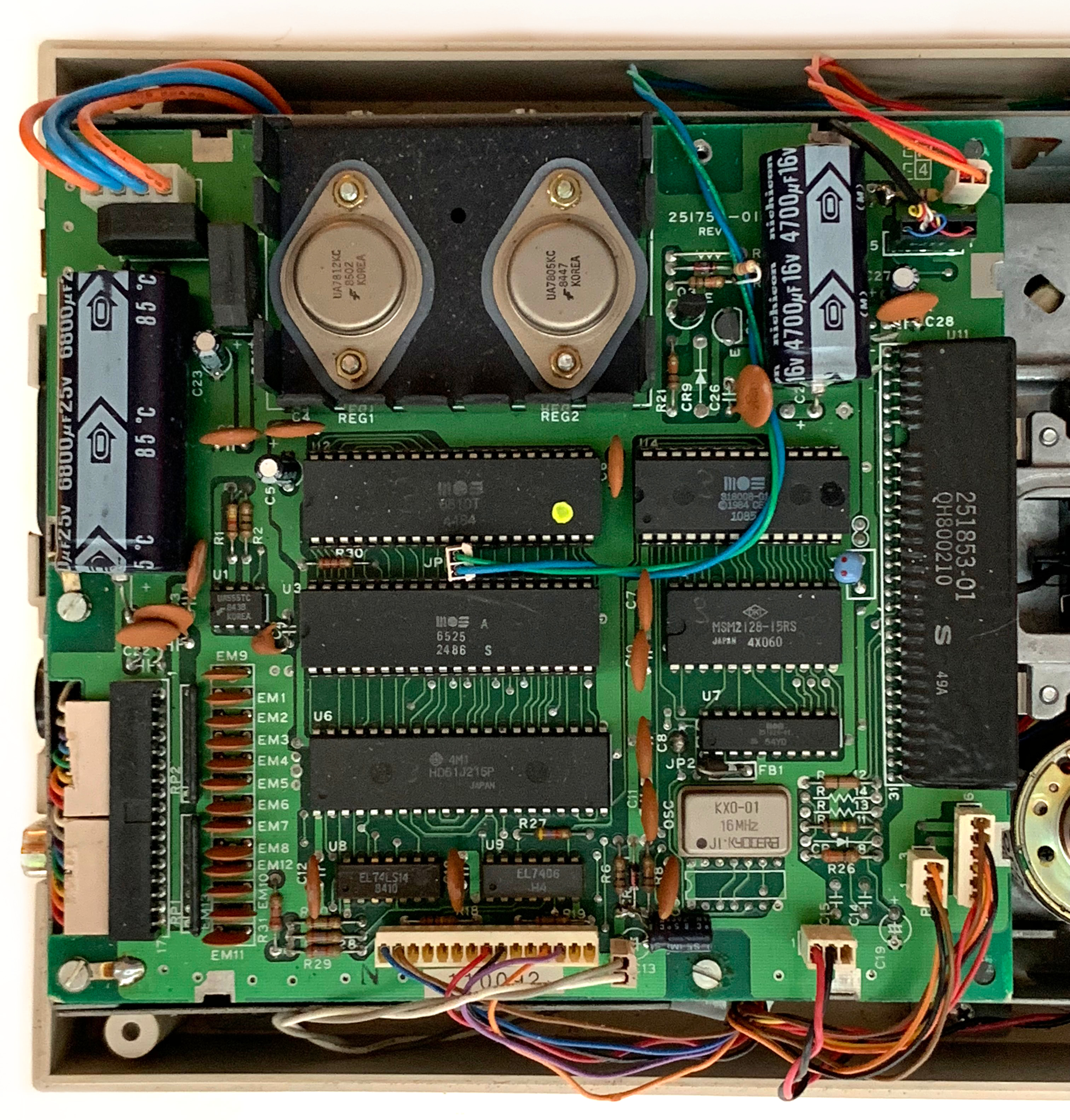
Here is a closeup of the 1551 board in the 1541. It contains a MOS 6510T CPU (2 MHz version of the C64’s 6510 CPU) and a MOS 6525 TPI I/O controller.
The top left connector is power. The four white connectors at the bottom and the black connector at the top lead to the drive mechanics and are just compatible between the 1541 and the 1551. The black cable on the left goes to the paddle.
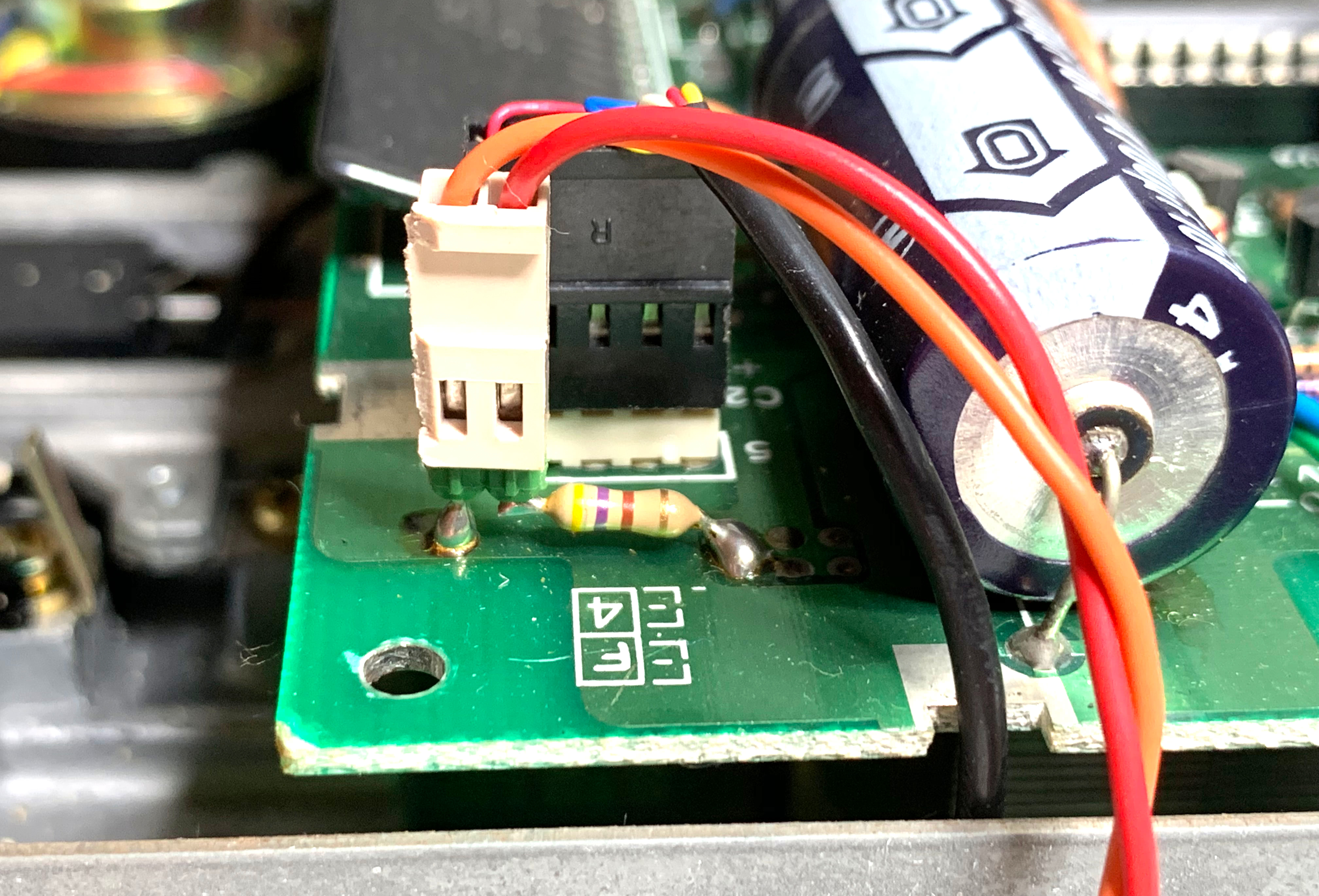
A standard 1551 does not have a switch to change the device number. Cutting the trace at JP1 would switch it from 8 to 9. Here, the trace is cut, and the yellow/white wires lead to the switch at the front.
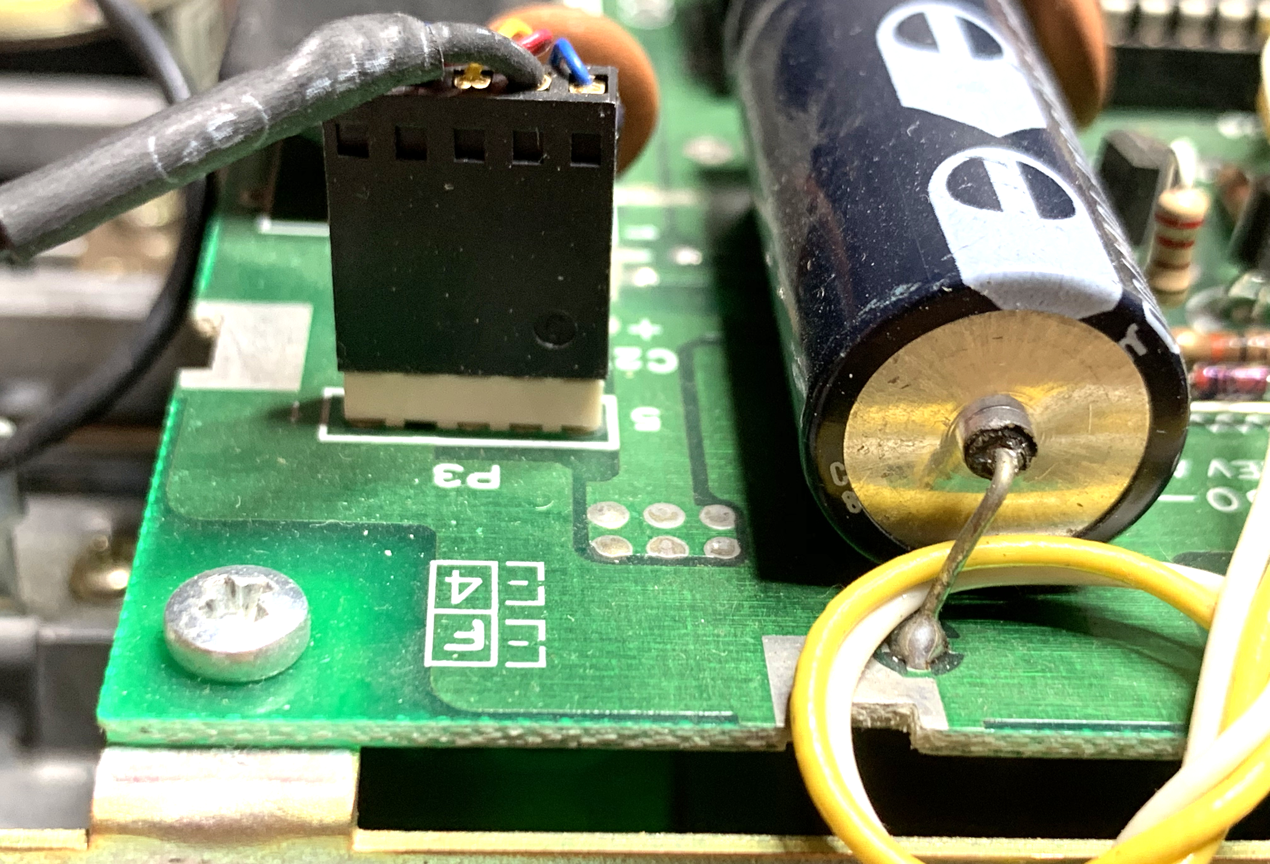
Things look similar in the 1570. JP1 is cut and connected here as well (blue/green) and goes to the toggle switch on the right of the front panel. But there are two more connectors: the orange/red one at the top right (drive number LED), and the white/gray one at the bottom center (reset button).
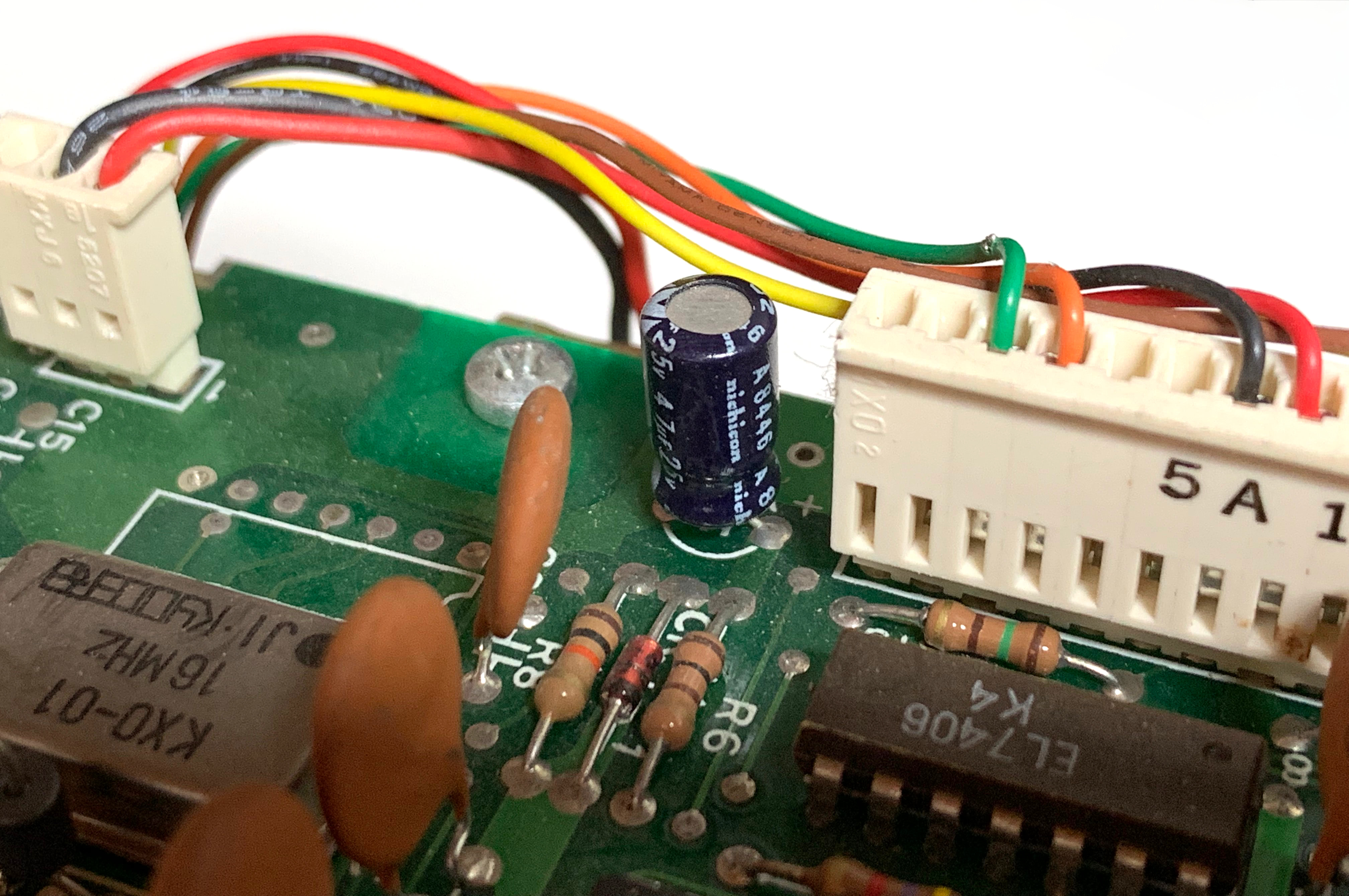
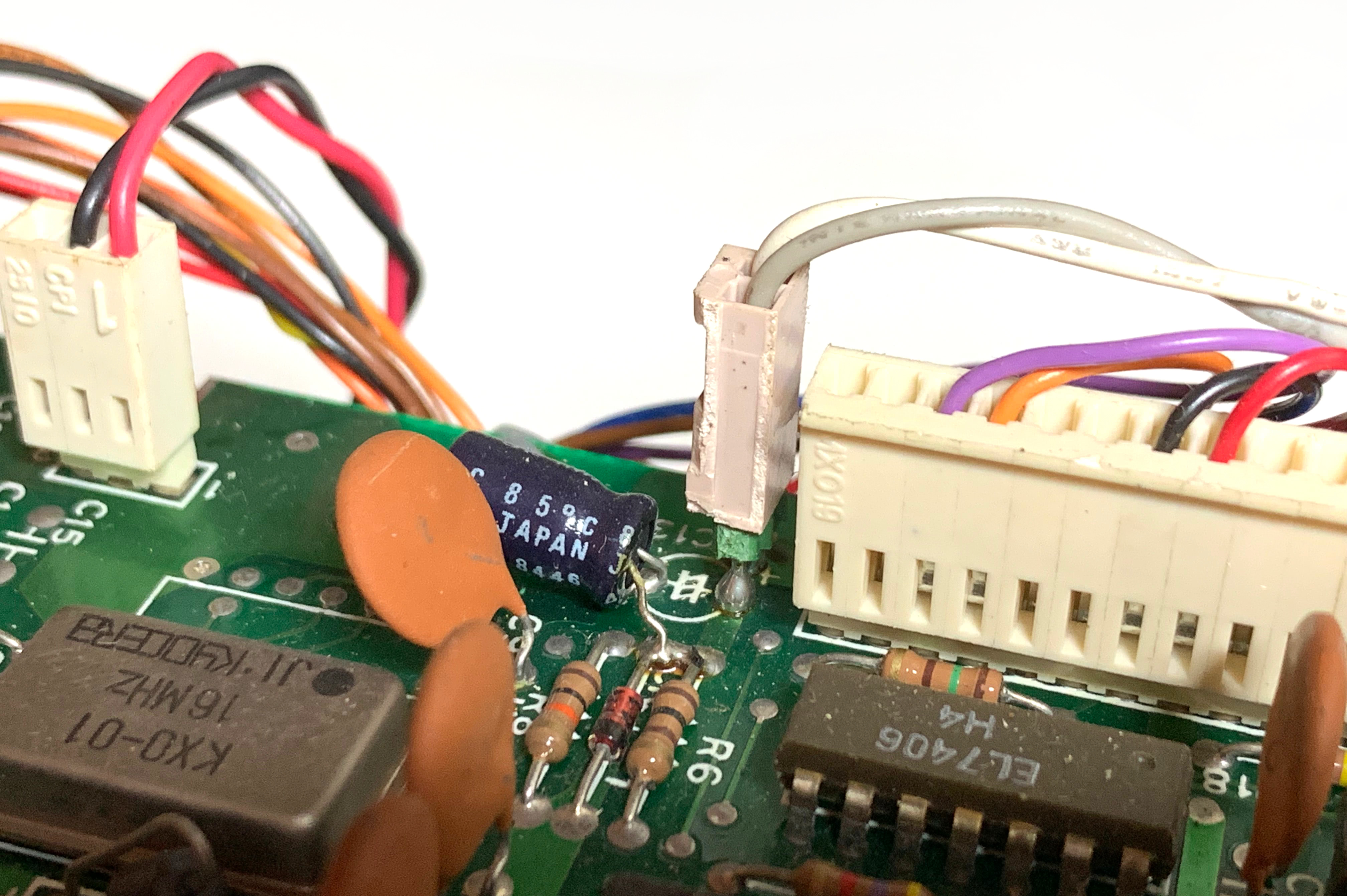
These pictures compare the unmodified board with the modified one. The white/gray wires move the capacitor C13 and add a header that leads to the button on the left of the front panel. Pressing the button causes a reset.
The newly added orange/red wires connect to the LED on the right of the front panel. The LED will show whether the device number is 8 or 9.
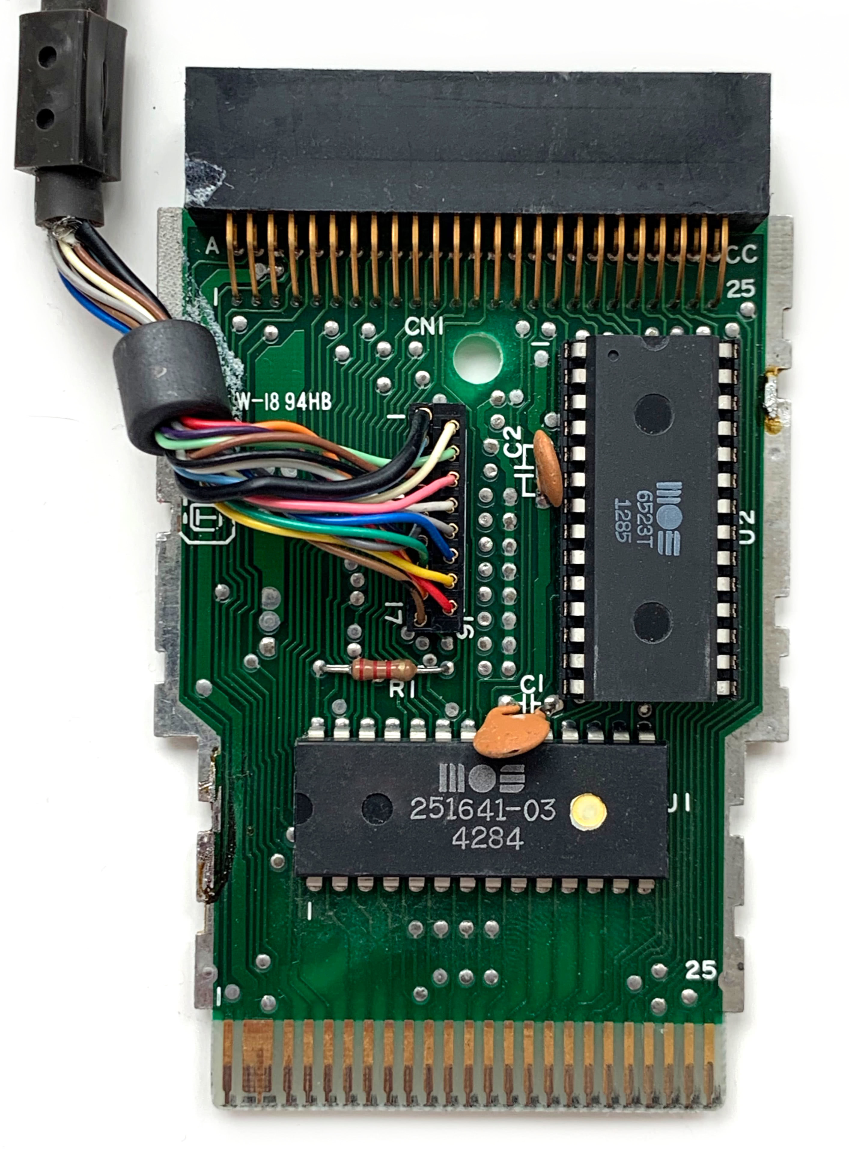
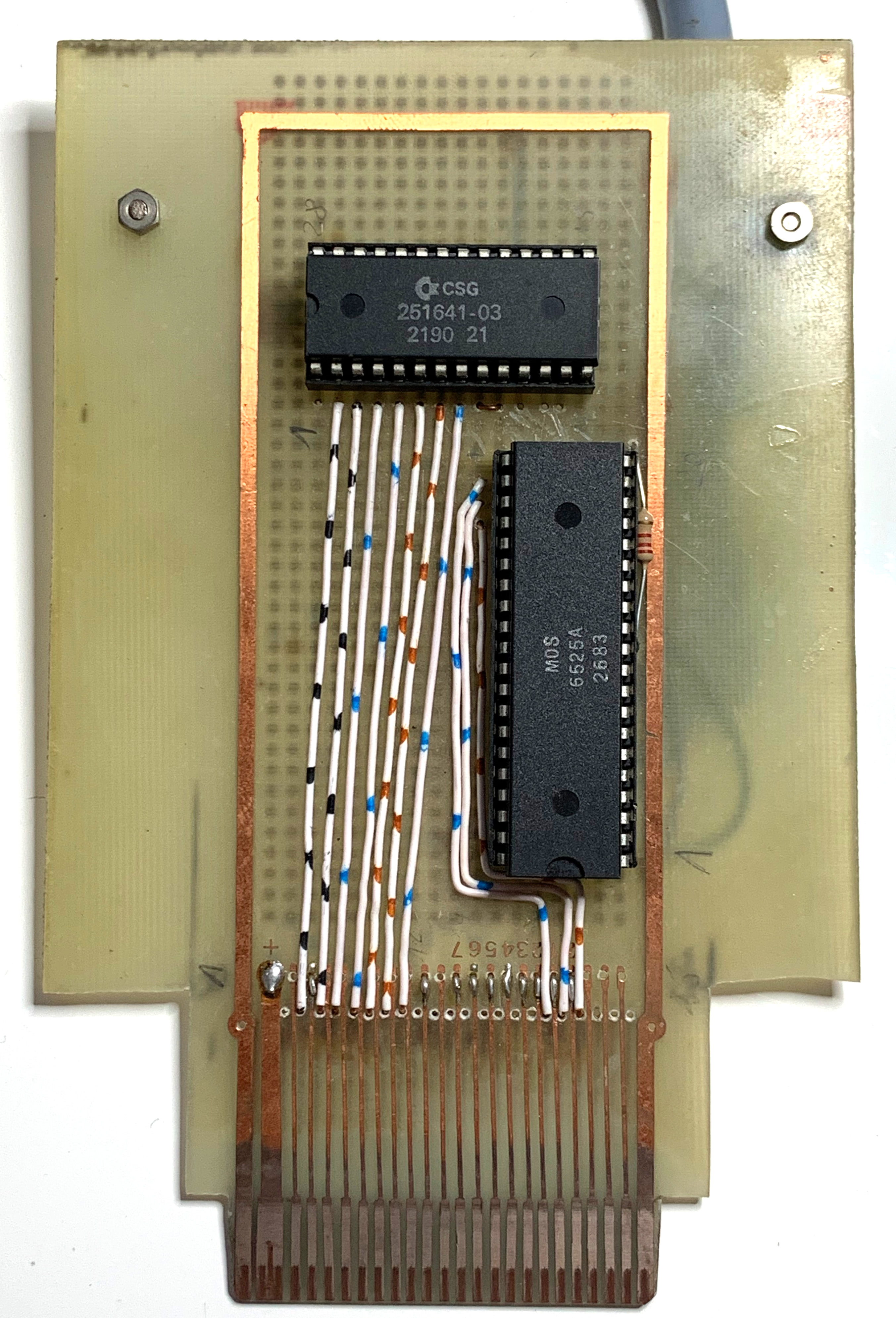
The modded 1541 uses a regular 1551 paddle. It contains a 251641-03 PLA and a 6523T TPI I/O controller. The 6323T TPI is a chip that was only ever used in the paddle. It is the DIP-28 version of the DIP-40 6525 TPI (used in the drive), i.e. the same die in a smaller package. The TPI has three times 8 GPIOs (PA, PB, PC), but on the 6523T version, only PA, PB0/1 and PC6/7 are exposed, which is just enough for the 12 wire TCBM protocol. In case the 6523T ever breaks, a full 6525 can be used in its place.
The PLA is the address decoder to map the TIA to either $FEC0 or $FEE0 in the computer’s address space. In case the PLA breaks, it can be replaced by a PLAdvanced or a SuperPLA V4.
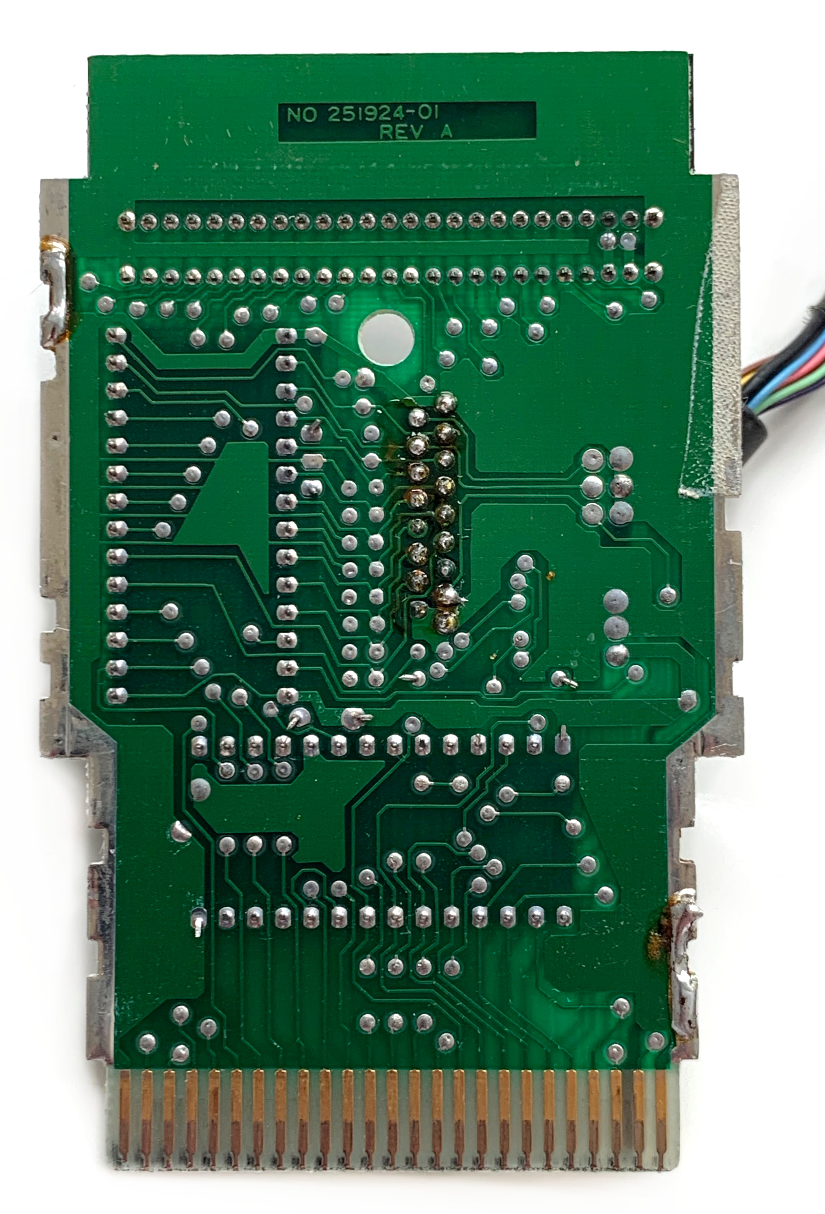
This is the back of the paddle.
The modded 1570 came with a hand-built paddle. It uses an original 251641-03 PLA with a date code of 2190. 1990 is very late for a chip that was only used in disk drives dicontinued not long after 1985. Commodore may have been producing it as a replacement part for quite a while1.
The TPI is the DIP-40 6525 described earlier. The extra pins are just not connected. The 6523T was probably not available as a replacement part from Commodore.
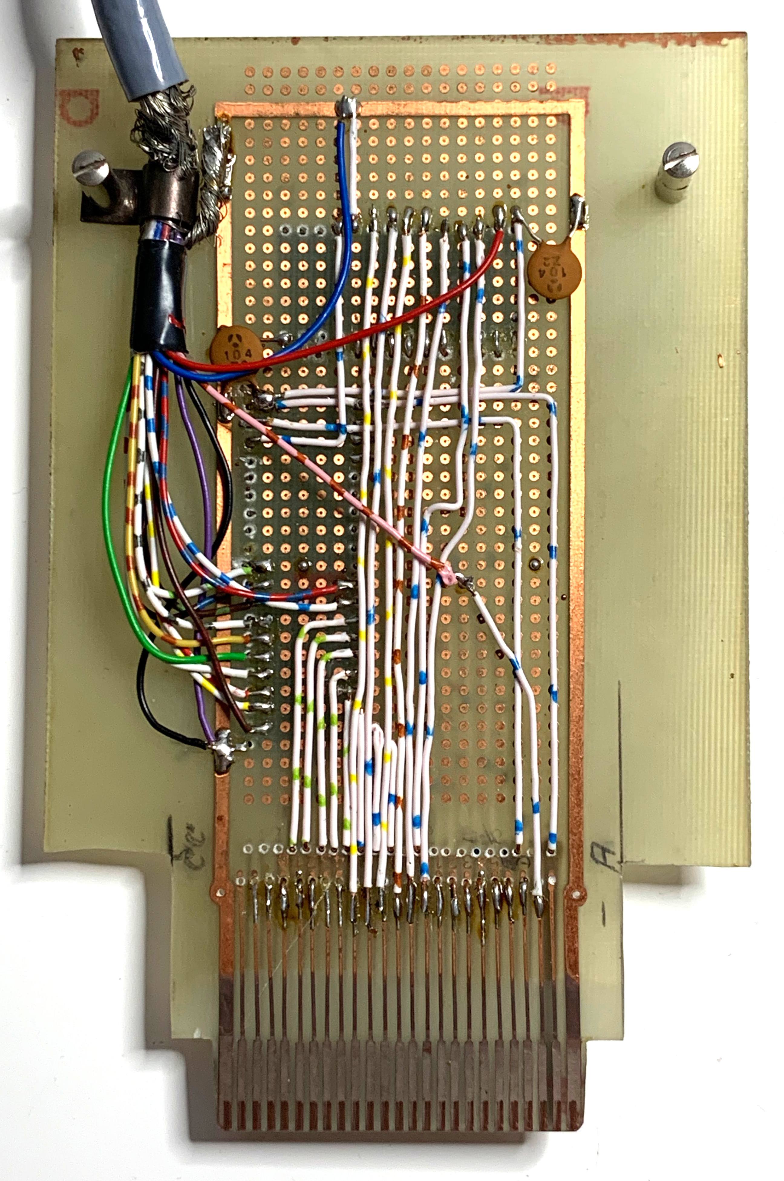
And here is the back of the hand-built paddle. The schematics are pretty simple. The original schematics exist, as well as a newer reverse-engineered version.
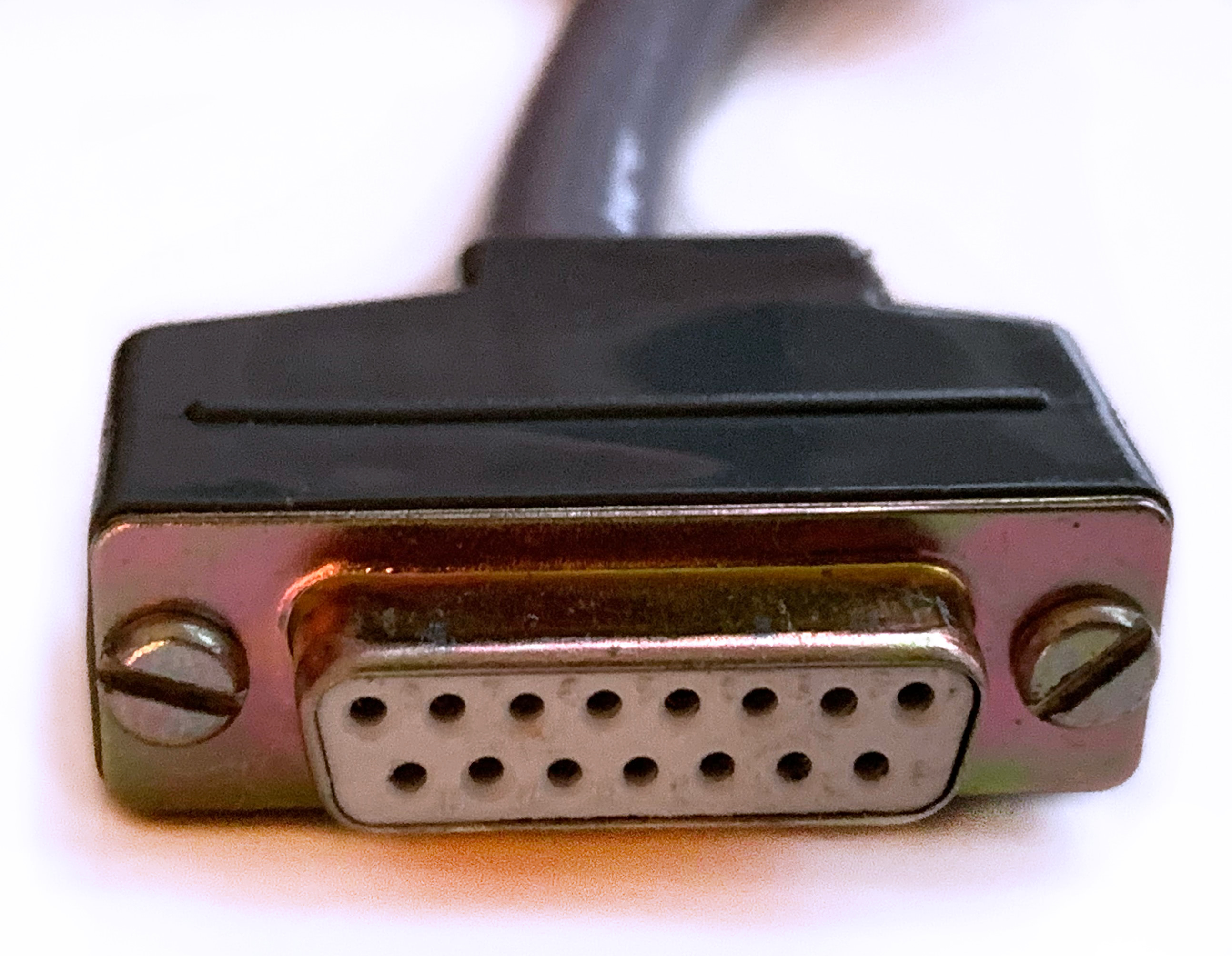
This is the DB15 connector used to connect the paddle to the drive.
Conclusion
The modded 1541 was most likely created by combining a 1551 that had dead mechanics with a 1541 that possibly had a dead board.
The 1570 was more likely modded from scratch. The 1551 board might have been available as a replacement part that could be ordered from Commodore. The paddle either wasn’t available as a replacement part, or was too expensive, so it was hand-built using Commodore replacement ICs.
The mechanics and the cases of both the 1541 and the 1570 are compatible with the 1551 electronics, so it is possible to revive a 1551 with dead mechanics, or even build a 1551 from a 1541/1570 and a 1551 board and some extra parts.
Things To Do
The 1570’s reset switch in the power LED and the 8/9 switch with an LED indicator are great modifications. It would be interesting to understand how they work using the schematics, and write instructions for modding other 1551-like devices like this.
-
PLA stands for “Programmable Logic Array”, so Commodore could easily create more of these chips at any time.↩
Are we even sure that the 1541 really is a modified 1541 and not rather a 1551 where the case got broken and thus got replaced with a 1541 case? Probably impossible to tell. The only other reasonable explanation for this mod might be that it had been done at the time when Commodore vintage computers had a really low value and someone found a 1551 for next to nothing while traveling and didn’t want to pay extra for carrying a complete drive when flying or something similar.
Hi!
I guess, this is the real 1541->1551 modifying:
https://www.vintageisthenewold.com/converting-a-1541-to-1551/
Yes, the original page language is Hungarian, and the guy gave us very details issues how to modify the 41 to 51. (Not replace the mechanic.)
Bye!
Can’t you put the power supply from a 1541 into a 1551 to convert it to 110V? It sounds like that would be an easier way to get a 1551 working in a 110V country.
This is a lovely project…. how about… trying the same hack with a 1581? 🙂