NES and SNES controllers support 8 to 12 buttons with only three data pins (plus VCC/GND). Let’s attach them to a C64 – or any 6502-based system!

NES Connector
The NES controller needs to be connected to +5V, GND and three GPIOs.
 ----------
| 5  6  7   \
| 4  3  2  1 |
 ------------
| Pin | Description |
|---|---|
| 1 | GND |
| 2 | CLK |
| 3 | LATCH |
| 4 | DATA |
| 5 | – |
| 6 | – |
| 7 | +5V |
SNES Connector
The SNES controller’s pins are just like the NES controller’s, but with a different connector.
 /---------------------
| 7  6  5 | 4  3  2  1 |
 \---------------------
| Pin | Description |
|---|---|
| 1 | +5V |
| 2 | CLK |
| 3 | LATCH |
| 4 | DATA |
| 5 | – |
| 6 | – |
| 7 | GND |
User Port
The C64 User Port exposes, among other lines, +5V, GND and 8 GPIOs (CIA#2 Port B):
 1 | 2  3  4  5  6  7  8  9  10 | 11 12
--- ---------------------------- -------
 A | B  C  D  E  F  H  J  K  L  | M  N
(viewed towards the C64 edge connector)
| Pin | Description |
|---|---|
| 1 | GND |
| 2 | +5V |
| C | PB0 |
| D | PB1 |
| E | PB2 |
| F | PB3 |
| H | PB4 |
| J | PB5 |
| K | PB6 |
| L | PB7 |
Connection
Let’s semi-arbitrarily map the signals like this:
| GPIO | Description |
|---|---|
| PB3 | LATCH (for both controllers) |
| PB4 | DATA (controller 1) |
| PB5 | CLK (for both controllers) |
| PB6 | DATA (controller 2) |
The latch and clock outputs go to both controllers. There is a data line for each controller.
So the connection diagram for two NES controllers looks like this:
| Description | User Port Pin | NES #1 Pin | NES #2 Pin | Color |
|---|---|---|---|---|
| GND | 1 | 1 | 1 | black |
| +5V | 2 | 7 | 7 | red |
| LATCH | F | 3 | 3 | blue |
| DATA#1 | H | 4 | – | green |
| CLK | J | 2 | 2 | white |
| DATA#2 | K | – | 4 | yellow |
And this is the same diagram for two SNES controllers:
| Description | User Port Pin | NES #1 Pin | NES #2 Pin | Color |
|---|---|---|---|---|
| GND | 1 | 7 | 7 | black |
| +5V | 2 | 1 | 1 | red |
| LATCH | F | 3 | 3 | blue |
| DATA#1 | H | 4 | – | green |
| CLK | J | 2 | 2 | white |
| DATA#2 | K | – | 4 | yellow |
In fact, you can attach an NES and an SNES controller in parallel for each of the two slots, as long as you ever only connect one controller per slot.
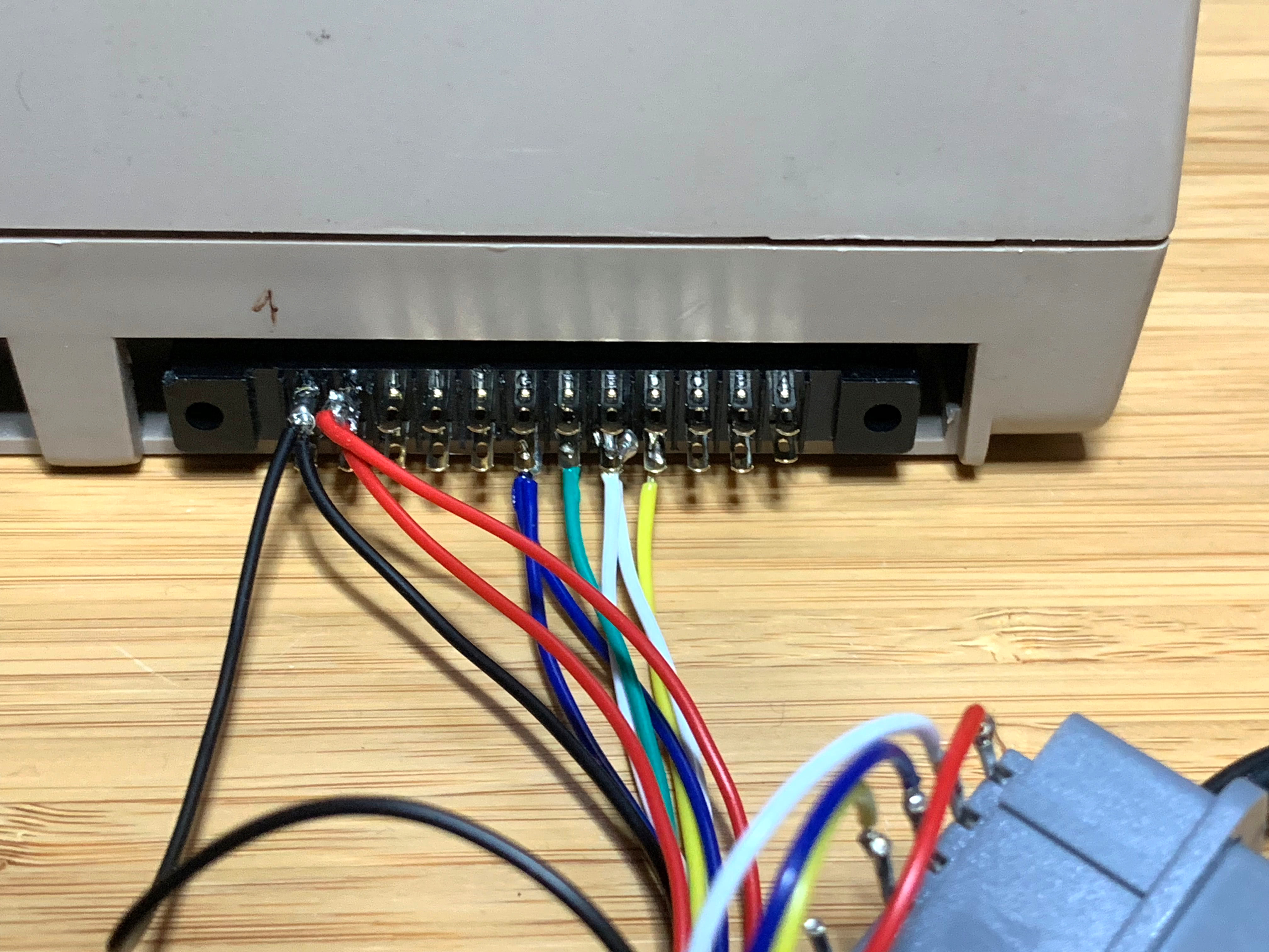
This is the user port connector with wires attached for two controllers, using the color scheme above:
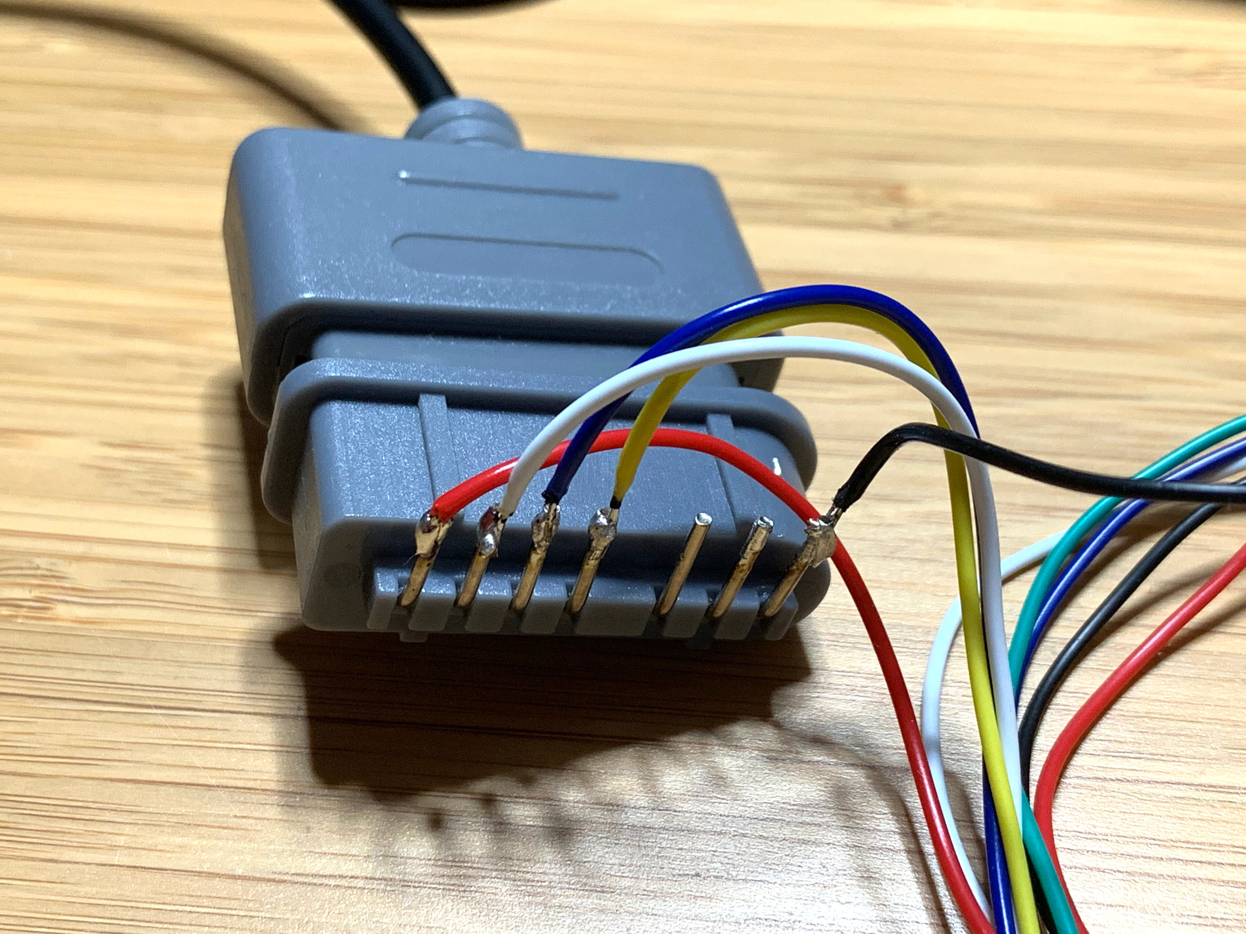
This is an NES connector attached as the first controller (green data line):
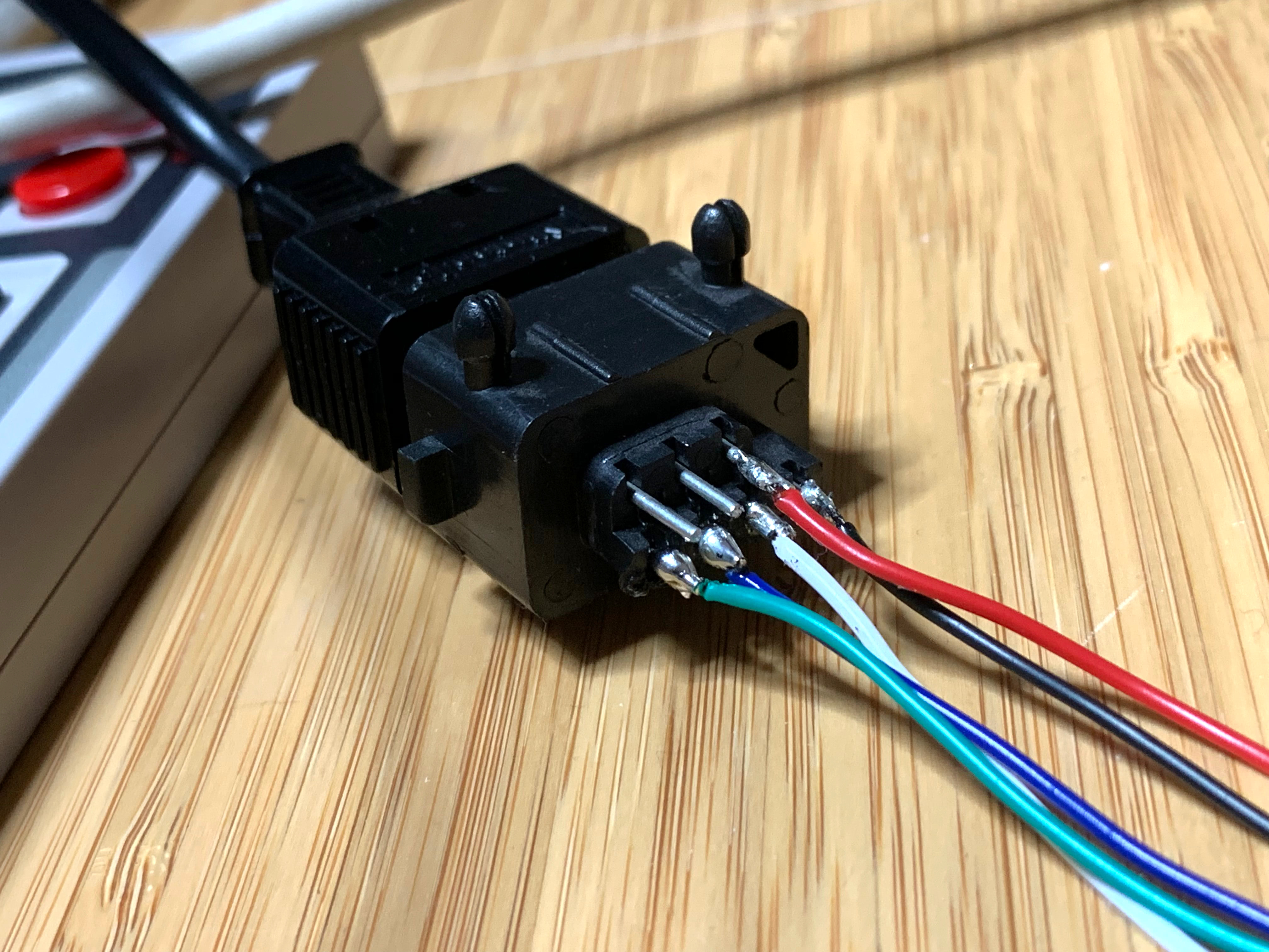
And this is an SNES connector attached as the second controller (yellow data line):
The Code
The code to read both controllers at a time is pretty simple:
; C64 CIA#2 PB
nes_data = $dd01
nes_ddr  = $dd03
;
bit_latch = $08 ; PB3 (user port pin F): LATCH (both controllers)
bit_data1 = $10 ; PB4 (user port pin H): DATA  (controller #1)
bit_clk   = $20 ; PB5 (user port pin J): CLK   (both controllers)
bit_data2 = $40 ; PB6 (user port pin K): DATA  (controller #2)

; zero page
controller1 = $e0 ; 3 bytes
controller2 = $f0 ; 3 bytes

query_controllers:
    lda #$ff-bit_data1-bit_data2
    sta nes_ddr
    lda #$00
    sta nes_data

    ; pulse latch
    lda #bit_latch
    sta nes_data
    lda #0
    sta nes_data

    ; read 3x 8 bits
    ldx #0
l2: ldy #8
l1: lda nes_data
    cmp #bit_data2
    rol controller2,x
    and #bit_data1
    cmp #bit_data1
    rol controller1,x
    lda #bit_clk
    sta nes_data
    lda #0
    sta nes_data
    dey
    bne l1
    inx
    cpx #3
    bne l2
    rts
After calling query_controllers, three bytes each at controller1 and controller2 will contain the state:
; byte 0:      | 7 | 6 | 5 | 4 | 3 | 2 | 1 | 0 |
;         NES  | A | B |SEL|STA|UP |DN |LT |RT |
;         SNES | B | Y |SEL|STA|UP |DN |LT |RT |
;
; byte 1:      | 7 | 6 | 5 | 4 | 3 | 2 | 1 | 0 |
;         NES  | 0 | 0 | 0 | 0 | 0 | 0 | 0 | 0 |
;         SNES | A | X | L | R | 1 | 1 | 1 | 1 |
; byte 2:
;         $00 = controller present
;         $FF = controller not present
A 0 bit means the button is pressed, 1 means it is released.
The code pulses LATCH once, which makes the controllers sample their button states and transmit the first bit through their respective DATA lines. Pulsing CLK 15 more times will make the controllers send the remaining bits. Since SNES controllers send 16 bits of data, but NES controllers only send 8 bits, the type of controller can be detected through the lowermost nybble of byte 1. Similarly, the presense of a controller is detected by continuing to read bits: If a controller is attached, it will send 0 bits.
Repository
The driver code, together with demo code for the C64 can be found at https://github.com/mist64/nes_snes_controller_6502.
More?
For each additional controller, only a single extra GPIO is needed. This way, six controllers would be possible on a single 8 bit I/O port, with only slightly modified code.
As a primitive hacker, I simply ripped out the guts of the nes controller, lobbed off the end of the cable and put on the “atari” style connector in its place. Then using a 2600, i pressed the up button and tried various wires with the common until the player character moved up, etc.
Of course this means that it can never go back to being a nes controller. Your solution is far more elegant, and is on a whole new level. Do you think though that theres a way to take your method and make an Interface to the two joystick ports instead? The c64 user port was rarely used, but it would be nice to have things attach where they are supposed to go.
Thanks for this. Nice work.
Pzombley – These mods are not replacing the standard joysticks. I don’t know enough about the inner workings of the CIA chips to know if you could mask the joystick controls with (some) of the NES inputs. A new game or demo would need to be written, or maybe some existing games could have their joystick routines altered.
There are two basic ways to use this technique to attach an unmodified (except for the connector) NES/SNES controller to the joystick ports on a C64:
1. Use a microcontroller to create an interface device that scans the NES gamepad using the same technique as used here, and based on that emulates the five buttons (fire and four directions) of an Atari joystick. An implementation of this, including schematics and source code, can be found here: https://www.instructables.com/id/Arduino-lets-you-play-Atari-2600-and-ZX-Spectrum-u/
2. Use this exact technique but with CIA 1 ports A and B on the C64, which are connected to the joystick ports instead of the user port. Unfortunately, this would result in interference if certain keys on the keyboard are pressed while you’re trying to scan the game controller, since the keyboard is also connected to these ports, and you’d also have to make sure that the ROM keyboard scan routine (which also manipulates these ports) is not being called.
Here are the details of how the joystick ports are connected to CIA 1 on the C64: https://retrocomputing.stackexchange.com/a/11191/7208
And here’s a question that may turn up some devices that actually used this technique: https://retrocomputing.stackexchange.com/q/12015/7208
The joystick X and Y axis are analogue (potentiometers) rather than simple on/off buttons, so it wouldn’t be possible without something to translate between data read from the control pads shift register and the signals the joystick port expects to see.
There are two basic ways to use this technique to attach an unmodified (except for the connector) NES/SNES controller to the joystick ports on a C64:
1. Use a microcontroller to create an interface device that scans the NES gamepad using the same technique as used here, and based on that emulates the five buttons (fire and four directions) of an Atari joystick. An implementation of this, including schematics and source code, can be found here: https://www.instructables.com/id/Arduino-lets-you-play-Atari-2600-and-ZX-Spectrum-u/
2. Use this exact technique but with CIA 1 ports A and B on the C64, which are connected to the joystick ports instead of the user port. Unfortunately, this would result in interference if certain keys on the keyboard are pressed while you’re trying to scan the game controller, since the keyboard is also connected to these ports, and you’d also have to make sure that the ROM keyboard scan routine (which also manipulates these ports) is not being called.
Here are the details of how the joystick ports are connected to CIA 1 on the C64: https://retrocomputing.stackexchange.com/a/11191/7208
And here’s a question that may turn up some devices that actually used this technique: https://retrocomputing.stackexchange.com/q/12015/7208
There is already a solution for SNES controller to C64 / Atari joystick ports.
See http://wiki.polyplay.xyz/doku.php/trapthem_controller
and you can buy this here: https://www.polyplay.xyz/Trap-Them-Controller-Commodore-64 .
This controller is supported by “Trap Them” game and will be supported in the upcoming Giana Sisters 30th Anniversary game.
Please tell me you did not gut an SNES to get the controller jacks.
No they’re readily available, for example:
#Aliexpress C$ 2.09 11%OFF | High quality 90 degree female 7 Pin connector part Socket Slot for Nintendo for SNES Game Console controller
https://a.aliexpress.com/_dXoyVmD
The “Trapthem” controller is basically using the interface “Ninja” came up with ages ago, see his IK+ release: https://csdb.dk/release/?id=3757
That’s odd that you write 8 then zero to strobe the controller, when on the NES you write 1 then 0. I understand why the port is no longer at $4016, but I don’t get why it’s suddenly 8 then 0 to strobe the keys. Is this due to how you wired in the controller?