How the Final Cartridge III Freezer works

by Daniël Mantione
64 Tips & Tricks [PDF]

Michael Angerhausen, Lothar Englisch, Klaus Gerits, Frank Thrun:
64 Tips & Tricks
Düsseldorf: Data Becker, 1984. (4. erweiterte und überarbeitete Auflage)
ISBN 3-89011-001-0.
(386 pages, 26 MB)
Danke an Dirk Wagner für die Bereitstellung des Buchs.
Brotkastenfreunde Interview
In Folge 017 des C64-Podcasts Brotkastenfreunde bin ich diesmal Gast.
Das Titelbild vom 64’er Sonderheft 2/85

Am 25. März 1985 kam das zweite 64’er Sonderheft mit dem Thema Abenteuerspiele raus. Genau 40 Jahre später ist es nun als HTML und PDF online verfügbar – im Kontext des Projekts 64er-magazin.de. Der Drachenreiter auf dem Original-Titelblatt ist der damals 18jährige Boris Schneider-Johne – wer genau schaut, wird auf der Website erkennen, dass wir das Bild aktualisiert haben:
64'er Magazin – mit 40 Jahren Verzögerung jetzt monatlich im Web
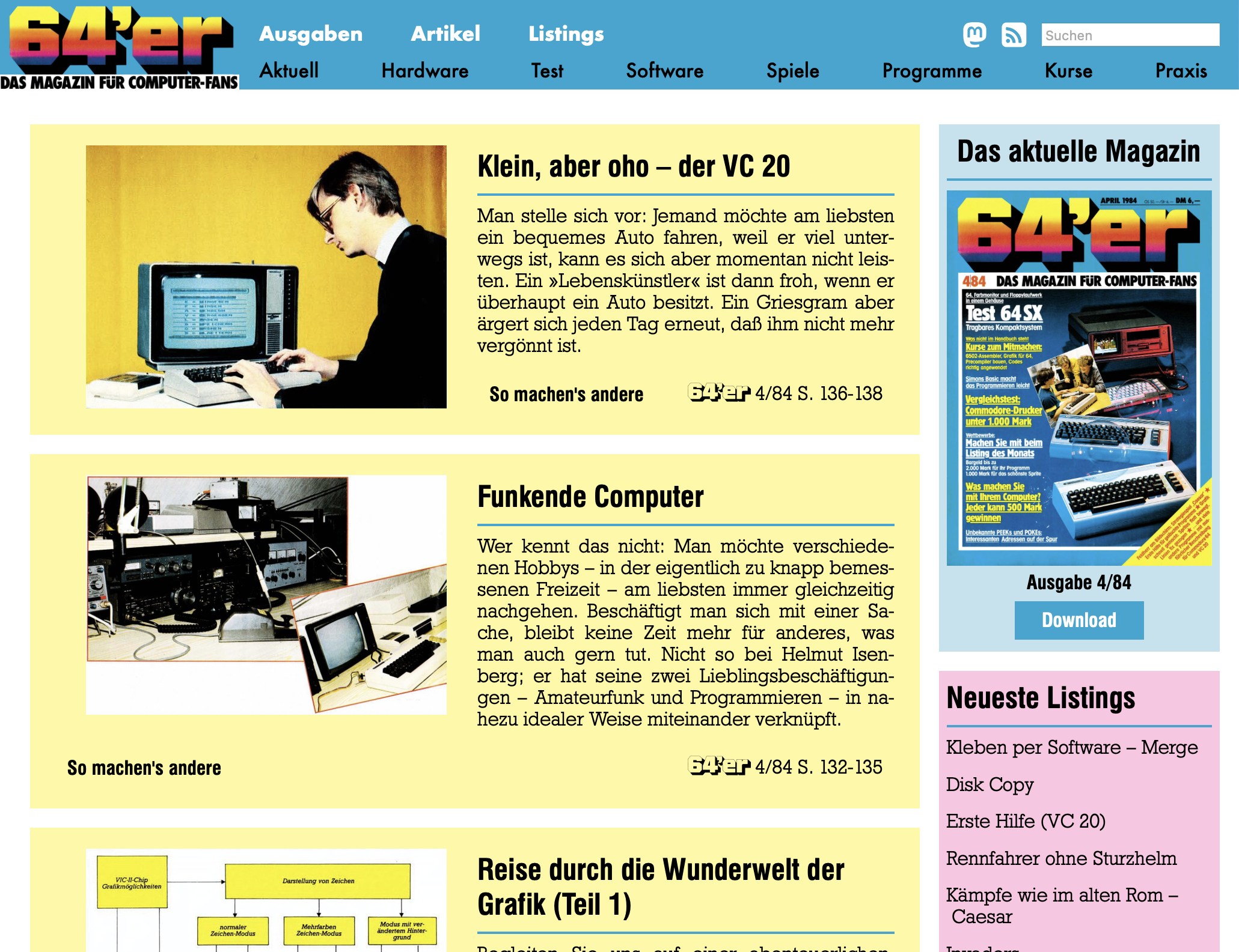
Zum 40jährigen Jubiläum des 64’er Magazins präsentieren wir das Kunstprojekt www.64er-magazin.de: eine Website, die so tut, als wäre 1984. Exakt 40 Jahre nach der ursprünglichen Veröffentlichung erscheint hier jeden Monat eine neue Ausgabe:
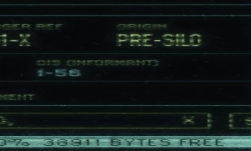
Silo S01E06: 38911 BYTES FREE
Scanntronik Manuals

The German company “Scanntronik” offered a lot of high-quality hardware and software for the Commodore 64 series computers, most in the space of graphics and desktop publishing. They are well-known for their Pagefox and Printfox software as well as their Handyscanner 64 hardware. This page offers most of the German-language manuals from across their product range as searchable PDFs.
The Commodore AUTOMODEM (Model 1650)

The Commodore 1650, also known as the “AUTOMODEM”, is Commodore’s first full modem directly connected to the phone line. It supports pulse dialing in software and 300 baud duplex connections.
The Commodore VICMODEM (Model 1600)
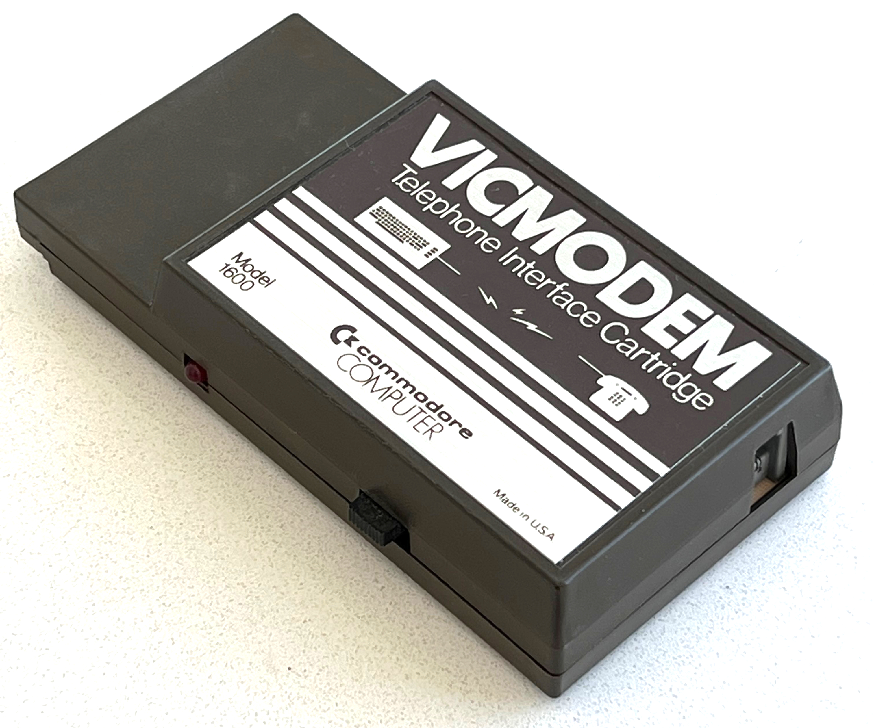
The Commodore 1600, also known as the “VICMODEM”, is Commodore’s very first modem (1982): It supports 300 baud duplex connections, and is connected to an existing telephone’s handset connector instead of the phone line. This kept the price down, but required the user to dial manually through the phone.
CCGMS Future 0.2
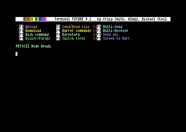
CCGMS Future 0.2 was just released. It adds 80 columns support, a true ASCII charset (in 80c mode), and bug fixes.
The Punter C1 Protocol
The Punter file transfer protocol (“New Punter”/“Punter C1”) is an alternative to the XMODEM family of protocols, which was and still is very popular on BBSes for Commodore computers. It is notorious for being badly documented. Let’s fix that.
UP9600: How to Bit-Bang 9600 Baud RS-232 on the C64
The user port of the Commodore 64 exposes a TTL-level RS-232 serial port that supports up to 1200 baud1. In 1997, Daniel Dallmann came up with a very sophisticated trick that allowed sending and receiving at 9600 baud2, using slightly different wiring and a dedicated driver. This “UP9600” wiring has become the de-facto standard for all modern accessories, like C64 WiFi modems. Let’s see how UP9600 works.
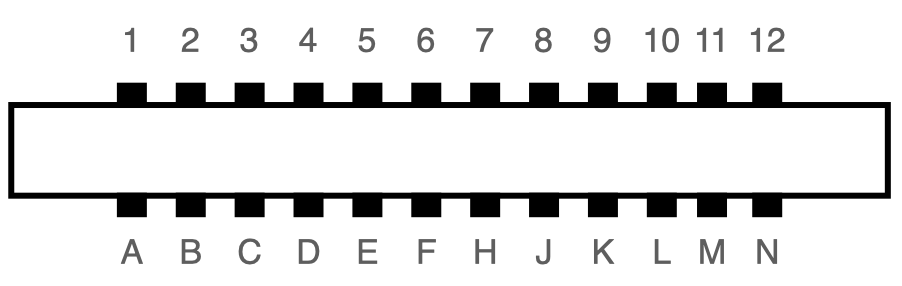
The Commodore Modem/1200 (Model 1670)
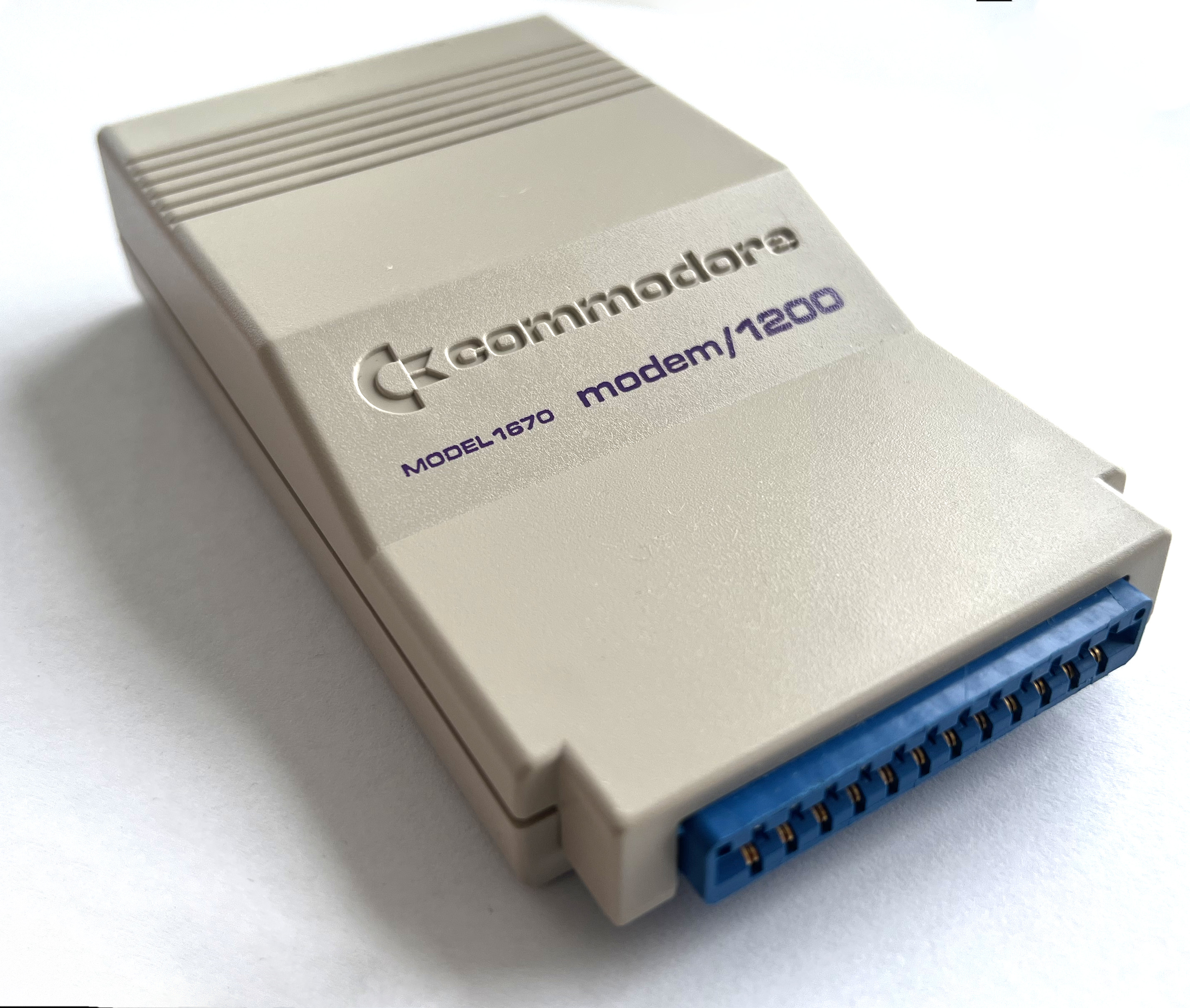
The Commodore 1670, also known as the “Modem/1200”, is Commodore’s first Hayes-compatible modem: It connects directly to the phone line and supports pulse and tone dialing for 1200 and 300 baud duplex connections. There were two revisions, the original 1670 and the “new” 1670, a.k.a. CR-1670. (The unit in this article is the later revision.)
The Commodore Modem/300 (Model 1660)

The Commodore 1660, also known as the “Modem/300”, is Commodore’s first full-featured modem: It connects directly to the phone line and supports pulse and tone dialing for 300 baud duplex connections.
Announcing CCGMS Future 0.1
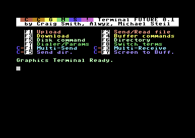
The CCGMS Terminal Program for the Commodore 64 is maintained again, and there is a new version: CCGMS Future 0.1, with bug fixes and new features.
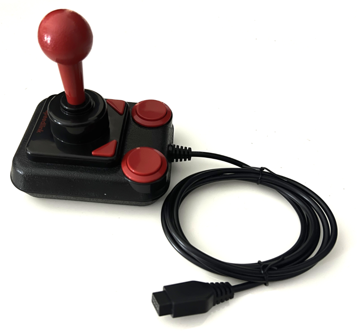
Free Joystick Extension Cable to Build Your DB9 Competition Pro

This article explains how to convert a “Competition Pro Extra USB” (which you can still buy new) to work with a C64, Amiga or Atari. For the conversion, you need a joystick extension cable like this:
[UPDATE] Converting the “Competition Pro Extra USB” to C64/Amiga/Atari DB9
I updated the instructions to a USB Competition Pro to DB9, so you can use it with a C64, Amiga etc. They now include the new “V3” and “V04T” pinouts and were updated with the use of a joystick extension cable.
The Ultimate Commodore 1541 Disk Drive Talk [video]
This is the video recording of “The Ultimate Commodore 1541 Disk Drive Talk” at VCF West 2021. As always, if you think it’s too fast, try watching it at 0.75x speed!
[Announcement] The Ultimate Commodore 1541 Disk Drive Talk @ VCFW 2021
After
Commodore's Assemblers: Part 5: 6502ASM
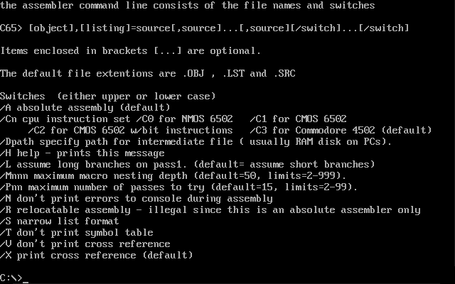
In the series about the assemblers Commodore used for developing the ROMs of their 8-bit computers, this article covers the 1989 “Commodore 6502 Assembler” (6502ASM), a cross-assembler written in C that ran on VAX and PC.